

Barracuda Backup Models 190, 290, 390, 490, and 690, and Barracuda Encrypted Backup Model 6090
Figure 1. Models 290, 390, 490, and 690, and Model 6090 Power and Disk Activity Indicator Lights. (See Figure 1a for Model 190.)
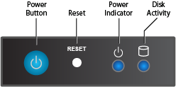
Table 1. Models 290, 390, 490, and 690, and Model 6090 Front Panel Power and Disk Activity Indicator Lights (See Table 1a for Model 190.)
| Component Name | Description |
|---|---|
| Power Button | Push to power on the Barracuda Backup appliance, and tap to safely reboot the appliance. |
| Reset Button | Push for 5 seconds to reset the Barracuda Backup appliance. |
| Power Light | Displays a solid blue light when the system is powered on. |
| Disk Light | Displays a solid green light and blinks during disk activity. |
Figure 1a. Model 190 Power and Disk Activity Indicator Lights
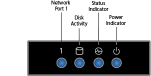
Table 1a. Model 190 Front Panel Power and Disk Activity Indicator Lights
| Component Name | Description |
|---|---|
| 1 | Displays a solid green light when the network port 1 is connected. |
| Disk Light | Displays a solid green light and blinks during disk activity. |
| Status Light | Displays status and blinks during activity such as backing up, etc. |
| Power Light | Displays a solid blue light when the system is powered on. |
Figure 2. Model 190 Rear Panel Ports and Connectors
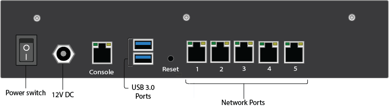
Table 2. Model 190 Rear Panel Rear Panel Port and Connector Description
| Port/Connector Name | Details |
|---|---|
| Power Switch | Power switch. |
| Power Supply | 12V DC. |
| Console | Console connection. |
| USB 3.0 Ports (2) | Optional. USB device connection. |
| Reset | Push for 5 seconds to reset the Barracuda Backup appliance. |
Network Ports (5) | Network connection. |
Figure 3. Model 290 Rear Panel Ports and Connectors
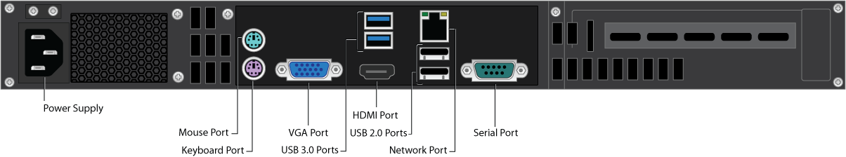
Table 3. Model 290 Rear Panel Rear Panel Port and Connector Description
| Port/Connector Name | Details |
|---|---|
| Power Supply | Power supply input. |
| Mouse Port | Optional. Mouse port. |
| Keyboard Port | Optional. PS2 keyboard connection. |
| VGA Port | Recommended. Video graphics array (VGA) monitor connection. |
| USB 3.0 Ports (2) | Optional. USB device connection. |
| HDMI Port | Optional. HDMI video connection. |
| USB 2.0 Ports (2) | Optional. USB device connection. |
| Network Port | Network connection. |
| Serial Port | Optional. Serial device connection. |
Figure 4. Model 390 Rear Panel Ports and Connectors
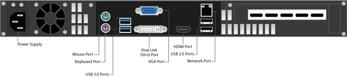
Table 4. Model 390 Rear Panel Rear Panel Port and Connector Description
| Port/Connector Name | Details |
|---|---|
| Power Supply(1) | Power supply input. |
| Mouse Port | Optional. Mouse port. |
| Keyboard Port | Optional. PS2 keyboard connection. |
| USB 3.0 Ports (2) | Optional. USB device connection. |
| Dual Link DVI-D Port | Optional. Digital monitor connection. |
| VGA Port | Recommended. Video graphics array (VGA) monitor connection. |
| HDMI Port | Optional. HDMI video connection. |
| USB 2.0 Ports (2) | Optional. USB device connection. |
| Network Port | Network port. |
| Note: (1)The C13 to C14 cable is standard for most rack setups as a power strip allows for the C14 connection. C13 to NEMA 5-15P is the standard for direct connections to a UPS. | |
Figure 5. Model 490 Rear Panel Ports and Connectors
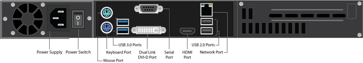
Table 5. Model 490 Rear Panel Rear Panel Port and Connector Description
| Port/Connector Name | Details |
|---|---|
| Power Supply | Power supply input.(1) |
| Power Switch | Power switch. |
| Mouse Port | Optional. Mouse port. |
| Keyboard Port | Optional. PS2 keyboard connection. |
| USB 3.0 Ports (2) | Optional. USB device connection. |
| Serial Port | Optional. Serial device connection. |
| Dual Link DVI-D Port | Optional. Digital monitor connection. |
| HDMI Port | Optional. HDMI video connection. |
| USB 2.0 Ports (2) | Optional. USB device connection. |
| Network Port | Network port. |
| Note: (1)The C13 to C14 cable is standard for most rack setups as a power strip allows for the C14 connection. C13 to NEMA 5-15P is the standard for direct connections to a UPS. | |
Figure 6. Model 690 and Model 6090 Rear Panel Ports and Connectors
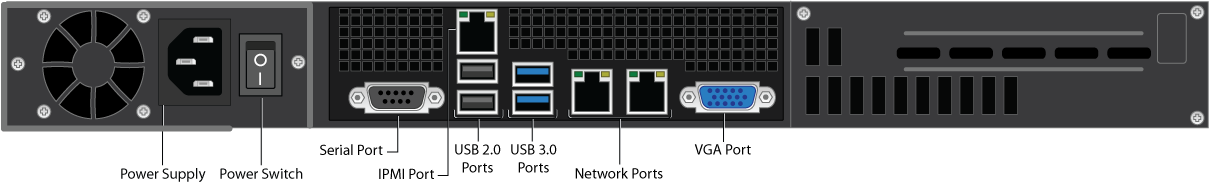
Table 6. Model 690 and Model 6090 Rear Panel Port and Connector Description
| Port/Connector Name | Details |
|---|---|
| Power Supply | Power supply input.(1) |
| Power Switch | Power switch. |
| Serial Port | Optional. Serial device connection. |
| IPMI Port | Intelligent Platform Management Interface (IPMI) port for device management over the network. |
| USB 2.0 Ports (2) | Optional. USB device connection. |
| USB 3.0 Ports (2) | Optional. USB device connection. |
| Network Ports (2) | Network connection.(2) |
| VGA Port | Recommended. Video graphics array (VGA) monitor connection. |
| 1 Gigabit Ethernet Card (Model 6090) | Network port. |
| 10 Gigabit Ethernet Card (Model 690) | If your organization's environment does not support 10 Gigabit throughput, the card reduces its speed to 1 Gigabit:
|
Notes: (2) Models 690/6090 and higher come with two network interfaces. One is active and the other is inactive, denoted by a plastic RJ45 connector in the port. The inactive port can be enabled in two ways. One, via NIC bonding which allows users to bond multiple network interfaces into a single channel; note that you must have two separate network connections and this is not to be used for one data pipe. Two, through traffic management. Manage the traffic that goes out of each NIC, that is, replication traffic through the default interface, and backup traffic through the secondary interface. To enable the inactive network interface, contact Barracuda Networks Technical Support. | |
Barracuda Backup Models 790 through 995, and Barracuda Encrypted Backup Models 8090 and 9090
Figure 7. Models 790 through 995, and Models 8090 and 9090 Power and Disk Activity Indicator Lights
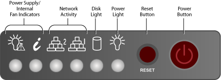
Table 7. Model 790 through 995, and Models 8090 and 9090 Rear Panel Port and Connector Description
| Component Name | Description |
|---|---|
| Power Supply/Internal Fan | Power supply and internal fan issue indicators:
|
| Network Activity (2) | Blinks green to indicate network activity. |
| Disk Light | Displays a solid orange light and blinks during disk activity. |
| Power Light | Displays a solid green light when the system is powered on. |
| Reset Button | Push for 5 seconds to reset the Barracuda Backup appliance. |
| Power Button | Push to power on the Barracuda Backup appliance, and tap to safely reboot the appliance. |
Figure 8. Models 790 and 890 Rear Panel Ports and Connectors
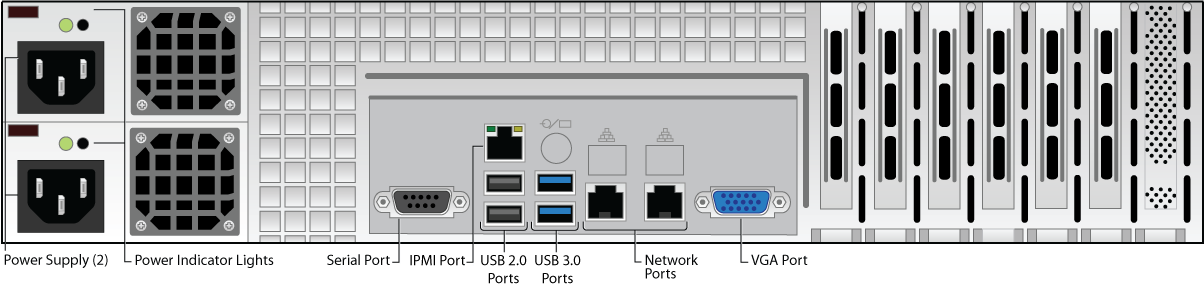
Table 8. Models 790 and 890 Rear Panel Port and Connector Description
| Port/Connector Name | Description |
|---|---|
| Power Supply (2) | Redundant power supply input.(1) |
| Power Indicator Lights | Displays based on power supply health:
|
| Serial Port | Optional. Serial device connection. |
| IPMI Port | IPMI port for device management over the network. |
| USB 2.0 Ports (2) | Optional. USB device connection. |
| USB 3.0 Ports (2) | Optional. USB device connection. |
| Network Ports (2) | Network connection.(3) |
| VGA Port | Recommended. Video graphics array (VGA) monitor connection. |
| 10 Gigabit Ethernet Card | If your organization's environment does not support 10 Gigabit throughput, the card reduces its speed to 1 Gigabit:
|
Notes: (2)The power supply may be degraded when, for example, one of the PSUs is not functioning. Push Reset; if this does not resolve the issue you may need to replace a PSU. (3) Models 690 and higher come with two network interfaces. One is active and the other is inactive, denoted by a plastic RJ45 connector in the port. The inactive port can be enabled in two ways. One, via NIC bonding which allows users to bond multiple network interfaces into a single channel; note that you must have two separate network connections and this is not to be used for one data pipe. Two, through traffic management. Manage the traffic that goes out of each NIC, that is, replication traffic through the default interface, and backup traffic through the secondary interface. To enable the inactive network interface, contact Barracuda Networks Technical Support. Contact Barracuda Networks Technical Support for additional troubleshooting. | |
Figure 9. Models 791 and 891 Rear Panel Ports and Connectors
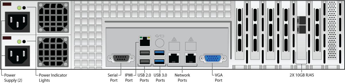
Table 9. Models 791 and 891 Rear Panel Port and Connector Description
| Port/Connector Name | Description |
|---|---|
| Power Supply (2) | Redundant power supply input.(1) |
| Power Indicator Lights | Displays based on power supply health:
|
| Serial Port | Optional. Serial device connection. |
| IPMI Port | IPMI port for device management over the network . |
| USB 2.0 Ports (2) | Optional. USB device connection. |
| USB 3.0 Ports (2) | Optional. USB device connection. |
| Network Ports (2) | Network connection.(3) |
| VGA Port | Recommended. Video graphics array (VGA) monitor connection. |
| 10 Gigabit Ethernet Card | If your organization's environment does not support 10 Gigabit throughput, the card reduces its speed to 1 Gigabit:
|
| 10 Gigabit Fiber Card | Optional . Use a small form-factor pluggable (SFP) transceiver module:
By default the top port is active. If you want to bond the two ports for 20 gigabit throughput with failover capabilities, Contact Barracuda Networks Technical Support. |
Notes: (2)The power supply may be degraded when, for example, one of the PSUs is not functioning. Push Reset; if this does not resolve the issue you may need to replace a PSU. (3) Models 690 and higher come with two network interfaces. One is active and the other is inactive, denoted by a plastic RJ45 connector in the port. The inactive port can be enabled in two ways. One, via NIC bonding which allows users to bond multiple network interfaces into a single channel; note that you must have two separate network connections and this is not to be used for one data pipe. Two, through traffic management. Manage the traffic that goes out of each NIC, that is, replication traffic through the default interface, and backup traffic through the secondary interface. To enable the inactive network interface, contact Barracuda Networks Technical Support. Contact Barracuda Networks Technical Support for additional troubleshooting. | |
Figure 10. Model 8090 Rear Panel Ports and Connectors
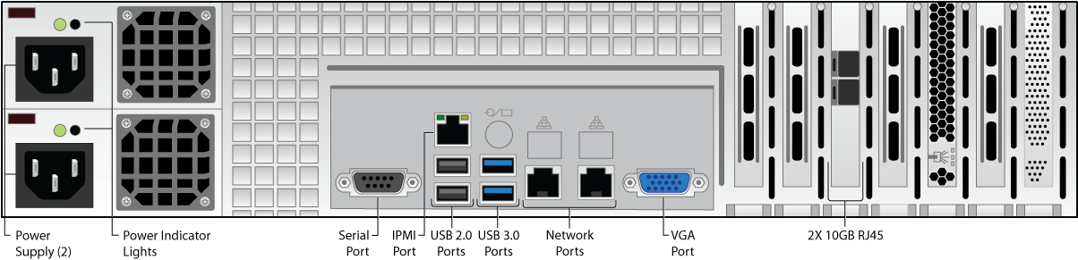
Table 10. Model 8090 Rear Panel Port and Connector Description
| Port/Connector Name | Description |
|---|---|
| Power Supply (2) | Redundant power supply input.(1) |
| Power Indicator Lights | Displays based on power supply health:
|
| Serial Port | Optional. Serial device connection. |
| IPMI Port | IPMI port for device management over the network. |
| USB 2.0 Ports (2) | Optional. USB device connection. |
| USB 3.0 Ports (2) | Optional. USB device connection. |
| Network Ports (2) | Network connection.(3) |
| VGA Port | Recommended. Video graphics array (VGA) monitor connection. |
| 10 Gigabit Ethernet Card | If your organization's environment does not support 10 Gigabit throughput, the card reduces its speed to 1 Gigabit:
|
Notes: (2)The power supply may be degraded when, for example, one of the PSUs is not functioning. Push Reset; if this does not resolve the issue you may need to replace a PSU. (3) Models 690 and higher come with two network interfaces. One is active and the other is inactive, denoted by a plastic RJ45 connector in the port. The inactive port can be enabled in two ways. One, via NIC bonding which allows users to bond multiple network interfaces into a single channel; note that you must have two separate network connections and this is not to be used for one data pipe. Two, through traffic management. Manage the traffic that goes out of each NIC, that is, replication traffic through the default interface, and backup traffic through the secondary interface. To enable the inactive network interface, contact Barracuda Networks Technical Support. Contact Barracuda Networks Technical Support for additional troubleshooting. | |
Barracuda Backup Models 895, 990, and 995
Figure 11. Models 895A, 990, and 995A Rear Panel Ports and Connectors
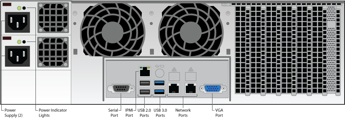
Table 11. Models 895A, 990, and 995A Rear Panel Port and Connector Description
| Port/Connector Name | Description |
|---|---|
| Power Supply (2) | Redundant power supply input.(1) |
| Power Indicator Lights | Displays based on power supply health:
|
| Serial Port | Optional. Serial device connection. |
| IPMI Port | IPMI port for device management over the network. |
| USB 2.0 Ports (2) | Optional. USB device connection. |
| USB 3.0 Ports (2) | Optional. USB device connection. |
| Network Ports (2) | Network connection.(3) |
| VGA Port | Recommended. Video graphics array (VGA) monitor connection. |
| 10 Gigabit Ethernet Card | If your organization's environment does not support 10 Gigabit throughput, the card reduces its speed to 1 Gigabit:
|
Notes: (2)The power supply may be degraded when, for example, one of the PSUs is not functioning. Push Reset; if this does not resolve the issue you may need to replace a PSU. (3) Models 690 and higher come with two network interfaces. One is active and the other is inactive, denoted by a plastic RJ45 connector in the port. The inactive port can be enabled in two ways. One, via NIC bonding which allows users to bond multiple network interfaces into a single channel; note that you must have two separate network connections and this is not to be used for one data pipe. Two, through traffic management. Manage the traffic that goes out of each NIC, that is, replication traffic through the default interface, and backup traffic through the secondary interface. To enable the inactive network interface, contact Barracuda Networks Technical Support. Contact Barracuda Networks Technical Support for additional troubleshooting. | |
Figure 12. Models 895B, 991, and 995B Rear Panel Ports and Connectors
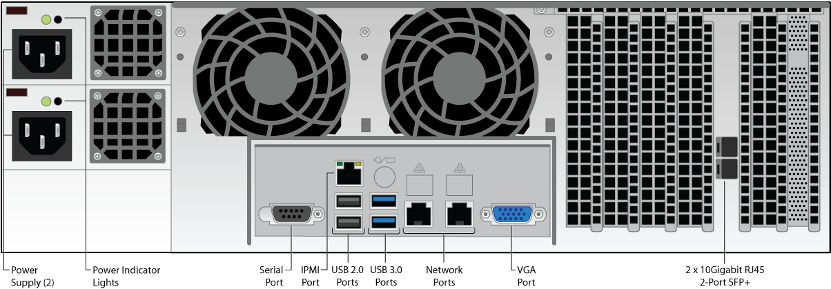
Table 12. Models 895B, 991, and 995B Rear Panel Port and Connector Description
| Port/Connector Name | Description |
|---|---|
| Power Supply (2) | Redundant power supply input.(1) |
| Power Indicator Lights | Displays based on power supply health:
|
| Serial Port | Optional. Serial device connection. |
| IPMI Port | IPMI port for device management over the network. |
| USB 2.0 Ports (2) | Optional. USB device connection. |
| USB 3.0 Ports (2) | Optional. USB device connection. |
| Network Ports (2) | Network connection.(3) |
| VGA Port | Recommended. Video graphics array (VGA) monitor connection. |
| 10 Gigabit Ethernet Card | If your organization's environment does not support 10 Gigabit throughput, the card reduces its speed to 1 Gigabit:
|
| 10 Gigabit Fiber Card | Optional . Use a small form-factor pluggable (SFP) transceiver module:
By default the top port is active. If you want to bond the two ports for 20 gigabit throughput with failover capabilities, Contact Barracuda Networks Technical Support. |
Notes: (2)The power supply may be degraded when, for example, one of the PSUs is not functioning. Push Reset; if this does not resolve the issue you may need to replace a PSU. (3) Models 690 and higher come with two network interfaces. One is active and the other is inactive, denoted by a plastic RJ45 connector in the port. The inactive port can be enabled in two ways. One, via NIC bonding which allows users to bond multiple network interfaces into a single channel; note that you must have two separate network connections and this is not to be used for one data pipe. Two, through traffic management. Manage the traffic that goes out of each NIC, that is, replication traffic through the default interface, and backup traffic through the secondary interface. To enable the inactive network interface, contact Barracuda Networks Technical Support. Contact Barracuda Networks Technical Support for additional troubleshooting. | |
Barracuda Encrypted Backup Model 9090
Figure 13. Model 9090 Rear Panel Ports and Connectors
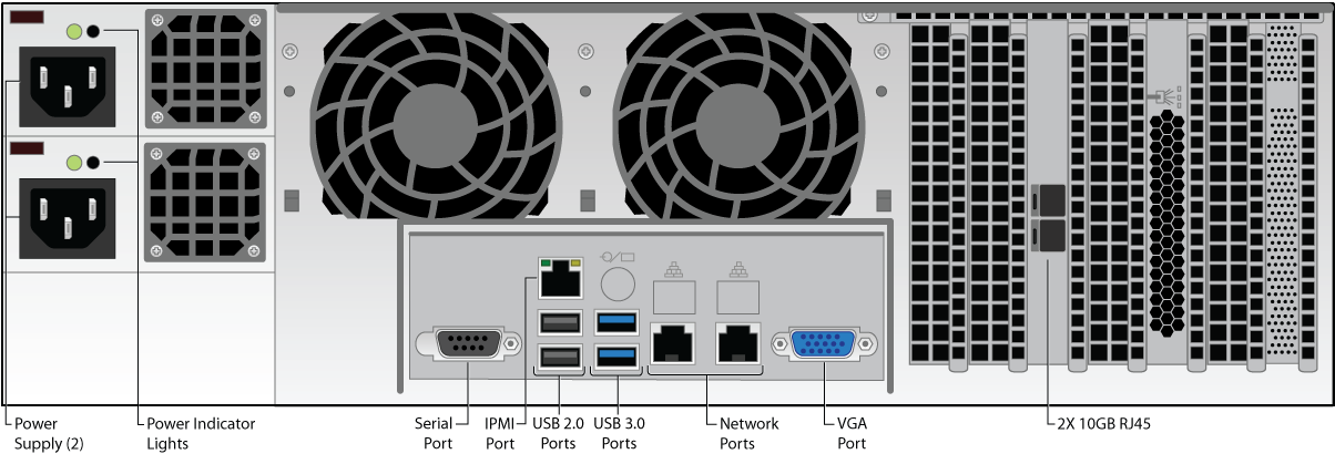
Table 13. Model 9090 Rear Panel Port and Connector Description
| Port/Connector Name | Description |
|---|---|
| Power Supply (2) | Redundant power supply input.(1) |
| Power Indicator Lights | Displays based on power supply health:
|
| Serial Port | Optional. Serial device connection. |
| IPMI Port | IPMI port for device management over the network. |
| USB 2.0 Ports (2) | Optional. USB device connection. |
| USB 3.0 Ports (2) | Optional. USB device connection. |
| Network Ports (2) | Network connection.(3) |
| VGA Port | Recommended. Video graphics array (VGA) monitor connection. |
| 10 Gigabit Ethernet Card | If your organization's environment does not support 10 Gigabit throughput, the card reduces its speed to 1 Gigabit:
|
Notes: (2)The power supply may be degraded when, for example, one of the PSUs is not functioning. Push Reset; if this does not resolve the issue you may need to replace a PSU. (3) Models 690 and higher come with two network interfaces. One is active and the other is inactive, denoted by a plastic RJ45 connector in the port. The inactive port can be enabled in two ways. One, via NIC bonding which allows users to bond multiple network interfaces into a single channel; note that you must have two separate network connections and this is not to be used for one data pipe. Two, through traffic management. Manage the traffic that goes out of each NIC, that is, replication traffic through the default interface, and backup traffic through the secondary interface. To enable the inactive network interface, contact Barracuda Networks Technical Support. Contact Barracuda Networks Technical Support for additional troubleshooting. | |
Barracuda Backup Models 1090, 1091, 1191, and Barracuda Encrypted Backup Model 10090
Figure 14. Models 1090, 1091, 1191, and Model 10090 Front Panel Power and Disk Activity Indicator Lights
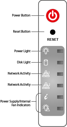
Table 14. Models 1090, 1091, 1191, and Model 10090 Front Panel Power and Disk Activity Indicator Lights
| Component Name | Description |
|---|---|
| Power Button | Push to power on the Barracuda Backup appliance, and tap to safely reboot the appliance. |
| Reset Button | Push for 5 seconds to reset the Barracuda Backup appliance. |
| Power Light | Displays a solid green light when the system is powered on. |
| Disk Light | Displays a solid orange light and blinks during disk activity. |
| Network Activity (2) | Blinks green to indicate network activity. |
| Power Supply/Internal Fan Indicators | Power supply and internal fan issue indicators:
|
Figure 15. Model 1090 Rear Panel Ports and Connectors
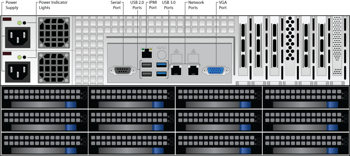
Table 15. Model 1090 Rear Panel Port and Connector Description
| Port/Connector Name | Description |
|---|---|
| Power Supply (2) | Redundant power supply input.(1) |
| Power Indicator Lights | Displays based on power supply health:
|
| Serial Port | Optional. Serial device connection. |
| USB 2.0 Ports (2) | Optional. USB device connection. |
| IPMI Port | IPMI port for device management over the network. |
| USB 3.0 Ports (2) | Optional. USB device connection. |
| Network Ports (2) | Network connection.(3) |
| VGA Port | Recommended. Video graphics array (VGA) monitor connection. |
| 10 Gigabit Ethernet Card | If your organization's environment does not support 10 Gigabit throughput, the card reduces its speed to 1 Gigabit:
|
Notes: (2)The power supply may be degraded when, for example, one of the PSUs is not functioning. Push Reset; if this does not resolve the issue you may need to replace a PSU. (3) Models 690 and higher come with two network interfaces. One is active and the other is inactive, denoted by a plastic RJ45 connector in the port. The inactive port can be enabled in two ways. One, via NIC bonding which allows users to bond multiple network interfaces into a single channel; note that you must have two separate network connections and this is not to be used for one data pipe. Two, through traffic management. Manage the traffic that goes out of each NIC, that is, replication traffic through the default interface, and backup traffic through the secondary interface. To enable the inactive network interface, contact Barracuda Networks Technical Support. Contact Barracuda Networks Technical Support for additional troubleshooting. | |
Figure 16. Model 1091 and 1191 Rear Panel Ports and Connectors.
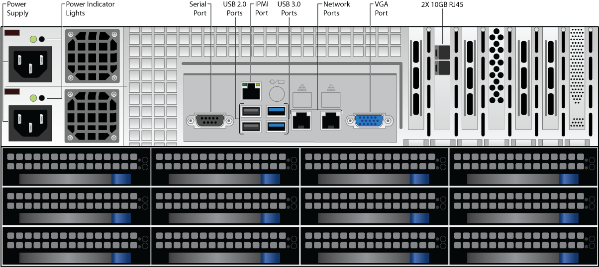
Table 16. Model 1091 and 1191 Rear Panel Port and Connector Description
| Port/Connector Name | Description |
|---|---|
| Power Supply (2) | Redundant power supply input.(1) |
| Power Indicator Lights | Displays based on power supply health:
|
| Serial Port | Optional. Serial device connection. |
| USB 2.0 Ports (2) | Optional. USB device connection. |
| IPMI Port | IPMI port for device management over the network. |
| USB 3.0 Ports (2) | Optional. USB device connection. |
| Network Ports (2) | Network connection.(3) |
| VGA Port | Recommended. Video graphics array (VGA) monitor connection. |
| 10 Gigabit Ethernet Card | If your organization's environment does not support 10 Gigabit throughput, the card reduces its speed to 1 Gigabit:
|
| 10 Gigabit Fiber Card | Use a small form-factor pluggable (SFP) transceiver module:
By default the top port is active. If you want to bond the two ports for 20 gigabit throughput with failover capabilities, Contact Barracuda Networks Technical Support. |
Notes: (2)The power supply may be degraded when, for example, one of the PSUs is not functioning. Push Reset ; if this does not resolve the issue you may need to replace a PSU. (3) Models 690 and higher come with two network interfaces. One is active and the other is inactive, denoted by a plastic RJ45 connector in the port. The inactive port can be enabled in two ways. One, via NIC bonding which allows users to bond multiple network interfaces into a single channel; note that you must have two separate network connections and this is not to be used for one data pipe. Two, through traffic management. Manage the traffic that goes out of each NIC, that is, replication traffic through the default interface, and backup traffic through the secondary interface. To enable the inactive network interface, contact Barracuda Networks Technical Support. Contact Barracuda Networks Technical Support for additional troubleshooting. | |
Figure 17. Model 10090 Rear Panel Ports and Connectors.
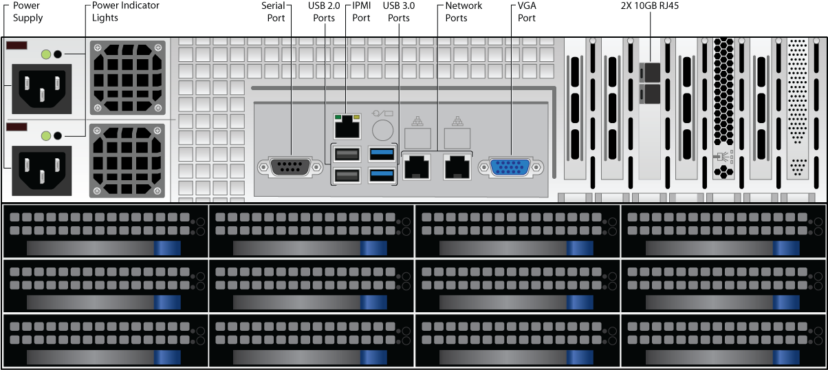
Table 17. Model 10090 Rear Panel Port and Connector Description
| Port/Connector Name | Description |
|---|---|
| Power Supply (2) | Redundant power supply input.(1) |
| Power Indicator Lights | Displays based on power supply health:
|
| Serial Port | Optional. Serial device connection. |
| USB 2.0 Ports (2) | Optional. USB device connection. |
| IPMI Port | IPMI port for device management over the network. |
| USB 3.0 Ports (2) | Optional. USB device connection. |
| Network Ports (2) | Network connection.(3) |
| VGA Port | Recommended. Video graphics array (VGA) monitor connection. |
| 10 Gigabit Ethernet Card | If your organization's environment does not support 10 Gigabit throughput, the card reduces its speed to 1 Gigabit:
|
| 10 Gigabit Fiber Card | Use a small form-factor pluggable (SFP) transceiver module:
By default the top port is active. If you want to bond the two ports for 20 gigabit throughput with failover capabilities, Contact Barracuda Networks Technical Support. |
Notes: (2)The power supply may be degraded when, for example, one of the PSUs is not functioning. Push Reset; if this does not resolve the issue you may need to replace a PSU. (3) Models 690 and higher come with two network interfaces. One is active and the other is inactive, denoted by a plastic RJ45 connector in the port. The inactive port can be enabled in two ways. One, via NIC bonding which allows users to bond multiple network interfaces into a single channel; note that you must have two separate network connections and this is not to be used for one data pipe. Two, through traffic management. Manage the traffic that goes out of each NIC, that is, replication traffic through the default interface, and backup traffic through the secondary interface. To enable the inactive network interface, contact Barracuda Networks Technical Support. Contact Barracuda Networks Technical Support for additional troubleshooting. | |