It seems like your browser didn't download the required fonts. Please revise your security settings and try again.
Barracuda Campus Help Center / Reference

1U 2 Bay Chassis Rack Mounting Instructions

  • Last updated on

The instructions in this article apply to the rack mountable 1U 2 Bay Barracuda SC811 chassis which is no longer distributed. For newer chassis, refer to the 1U Chassis Rack (Four Screw) Mounting Instructions or 1U Chassis Rack (Two Screw) Mounting Instructions.

This article refers to rack mountable 1U 2 Bay Barracuda SC811 chassis with provided rails that fit a rack between 29" and 35.25" in depth; for a complete list of appliances by model, see Rack Installation of Barracuda Appliances.

Rack assembly differs depending on the model of rack unit in your environment. Before rack mounting the appliance, review the installation instructions that accompany your rack unit for detailed rack setup instructions.

Before Getting Started

  • Verify that you have the rail kit included with your appliance, including:
    • Hardware to assemble the rails
    • Two sets of rail assemblies
    • Two rail mounting brackets
  • Cage nuts and screws to attach the appliance to your rack; these are not included with your appliance;
  • Verify that you have the rail kit included with your appliance;
  • Verify the rack unit is set up in a Restricted Access Location, for example, dedicated equipment rooms, service closets, and other secure, clean, dust-free well ventilated environments;
  • Allow enough clearance in front of the rack to allow the front door to open completely (~25 inches);

  • Verify approximately 30 inches of clearance is available in the back of the rack to allow for sufficient airflow and ease of servicing;
  • Verify the area does not generate heat, electrical noise, or electromagnetic fields;
  • A grounded power outlet is available.
  • Ensure the leveling jacks on the bottom of the rack are fully extended to the floor with the full weight of the rack resting on them.
  • In a single rack installation, stabilizers should be attached to the rack.
  • In multiple rack installations, the racks should be coupled together.
  • Verify the rack is stable before extending a component from the rack.
  • Extend only one component at a time; extending two or more simultaneously may cause the rack to become unstable.

Review the electrical and general safety precautions that came with the components you are adding to the chassis. Determine the placement of each component in the rack before you install the rails. Install the heaviest appliance components on the bottom of the rack first, and then work upwards.

Use a regulating uninterruptible power supply (UPS) to protect the appliance from power surges, voltage spikes, and to keep your system operating in case of a power failure. Allow the hot plug hard drives and power supply modules to cool before touching them. Always keep the rack's front door and all panels and components on the appliances closed when not servicing to maintain proper cooling.

  • Ambient Operating Temperature – If installed in a closed or multi-unit rack assembly, the ambient operating temperature of the rack environment may be greater than the ambient temperature of the room. Therefore, consideration should be given to installing the equipment in an environment compatible with the manufacturer's maximum rated ambient temperature (Tmra).
  • Proper Airflow and Mechanical Loading – Mount equipment into a rack so that the amount of airflow required for safe operation is not compromised and to prevent any hazardous condition that can arise due to uneven mechanical loading.
  • Circuit Overloading – Consideration should be given to the connection of the equipment to the power supply circuitry and the effect that any possible overloading of circuits might have on overcurrent protection and power supply wiring. Appropriate consideration of equipment nameplate ratings should be used when addressing these concerns.
  • Reliable Ground – To ensure a reliable ground at all times, the rack itself should be grounded. Particular attention should be given to power supply connections other than the direct connections to the branch circuit (i.e. the use of power strips, etc.).

Inspect the Packaging

Before getting started, inspect the shipping box and note if there is any damage. If the chassis itself shows any damage, file a damage claim with the carrier who delivered your Barracuda Networks appliance.

Install the Appliance in the Rack

Refer to the installation instructions that came with the rack unit you are using for detailed instructions; these rails fit a rack between 26" and 33.5" deep.

Identify the Rack Rail Sections

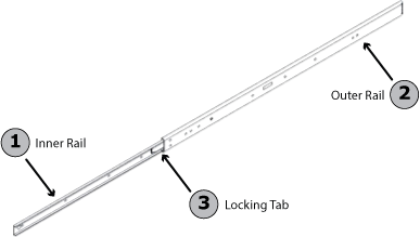
The chassis package includes two rack rail assemblies in the rack mounting kit. Each assembly consists of two sections: an inner fixed chassis rail that secures directly to the appliance chassis, and an outer fixed rack rail that secures directly to the rack itself.

Note that the cage nuts and screws to attach the appliance to your rack are not included with your appliance.


  1. Pull the inner rail (1) from the outer rail (2) as far as possible.
  2. Depress the locking tab (3), and pull the inner rail completely out.
  3. Repeat steps 1 and 2 with the other rail.

Figure 1. Inner and Outer Rack Rail Sections.

2bay-1u-chassis_rails.png
Lock the Appliance into Place

Both chassis rails have a locking tab. The tabs lock the appliance into place when it is installed and pushed fully into the rack. These tabs also lock the appliance into place when fully extended from the rack so as to prevent the appliance from coming completely out of the rack when pulled out for servicing.

Figure 2. Rail Installation.
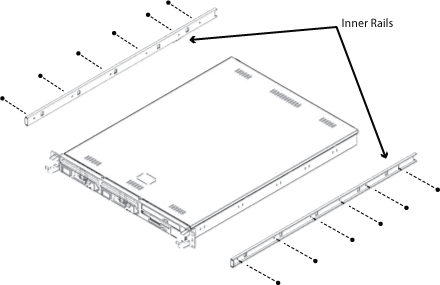
2bay-1u-chassis_locking_tabs.png

Install Inner Rail
  1. Align the chassis rail with the side of the chassis.
  2. Secure the rail to the chassis using six M5 flat head screws.
  3. Repeat steps 1 and 2 with the other side of the chassis.

Figure 3. Rack Brackets.

2bay-1u-chassis_rack_brackets_illo.png


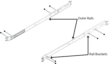
Install the Outer Rails to the Rack
  1. Confirm that the inner rails have been separated from the outer rails.
  2. Locate the rail brackets in the accessories box. The chassis package includes four rail brackets and two chassis mounts. The rail brackets have long ovals used to adjust the position of the rails when mounting, and the chassis mounts (both short) have one square hole.
  3. Secure the short brackets to the front of the outer rails with two M4 screws.
  4. Secure the long brackets to the outer rails using two M4 screws; tighten the screws loosely so the bracket can slide back and forth.
  5. Position the outer rail and brackets in the rack at the desired level.
  6. Secure the front of the rail to the rack using two M5 rack screws.
  7. Slide the rear bracket so that it fits snuggly into the rack. Secure the rear bracket to the rack using two M5 screws.
  8. Tighten the screws that secure the rear bracket to the rail.
  9. Repeat steps 1 through 8 with the other chassis rail.

The rack stabilizing mechanism must be in place or the rack must be bolted to the floor before you slide the unit out for servicing. Failure to stabilize the rack may cause the rack to tip over. 

Install the Chassis in the Rack
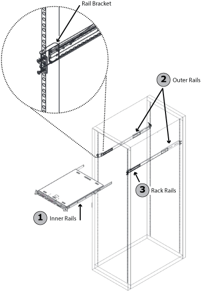
  1. Confirm that the chassis includes the inner rails (1) and that the outer rails (2) are installed on the rack.
  2. Align the chassis rails (1) with the front of the rack rails (3).
  3. Slide the chassis rails into the rack rails, keeping the pressure even on both sides (you may have to depress the locking tabs when inserting). When the server has been pushed completely into the rack, you should hear the locking tabs "click".
  4. (Optional) Insert and tighten the thumbscrews that hold the front of the server to the rack.

    Do not pick the server up by the front handles; the handles are designed to pull the system from a rack only. Always install servers into racks from the bottom up.


    Figure 4. Install the Chassis.

mounting-the-chassis.png


For detailed configuration steps, refer to the Getting Started section for the rack mounted appliance.