When configuring a virtual router instance for a CC-managed HA pair, the configuration is transparently transferred to the secondary firewall after being completed for the primary firewall. There is no need to make any configuration for the secondary firewall.
Before You Begin
Verify that two firewalls are operating in high availability mode. For more information, How to Set Up a Managed High Availability Cluster from Scratch.
Configuration
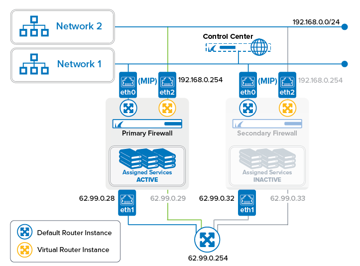
In the following example, an additional virtual instance will be created that routes traffic between a private network (e.g., 192.168.0.0/24) and the Internet. In this setup, the firewall service will be transparent to the additional virtual router instance only if authenticated users are not defined. All other services are not available to the additional virtual router. For more information on which services are available for additional virtual instances, see Virtual Routing and Forwarding (VRF).
Step 1. On the CC, Create a Virtual Router Instance for the Primary Firewall
When creating a router instance for the primary firewall, the configuration will be mirrored to the secondary firewall.
- Log into the Control Center.
- Right-click CONFIGURATION > Configuration Tree > Multi Range > your range > your cluster > Boxes > your primary firewall > Network.
- Select Lock.
- Right-click CONFIGURATION > Configuration Tree > Multi Range > your range > your cluster > Boxes > your primary firewall > Network.
- Select Create VR Instance from the list.
- The Create a new VR Instance window is displayed.
- The window for naming the virtual router is displayed.
- Enter the name for the virtual router, e.g.,
VR01. - Click OK.
- Click Send Changes.
- The Activate Changes window opens.
- Click Activate.
| VR Node configured in Control Center | VR Node on Managed Primary Firewall | VR Node on Managed Secondary Firewall |
|---|---|---|
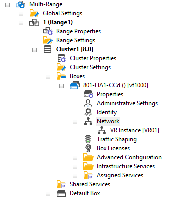 | 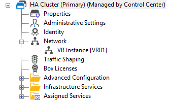 |  |
Step 2. Assign Interfaces to the VR Instance
The configuration for the interfaces will be forwarded from the primary to the secondary HA partner.
- On your Control Center, double-click CONFIGURATION > Configuration Tree > Multi Range > your range > your cluster > Boxes > your primary firewall > Network.
- In the left menu bar, click Virtual Router.
- Click Lock.
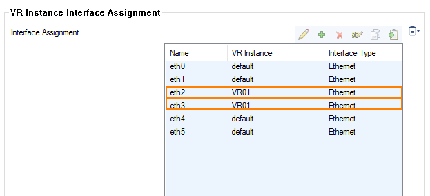
- In the Interface Assignment list, double-click the first interface to assign the VR Instance, e.g., eth2.
- The Interface Assignment window is displayed.
- For VR Instance, select VR01.
- Click OK.
- In the Interface Assignment list, double-click the second interface to assign the VR Instance, e.g., eth3.
- The Interface Assignment window is displayed.
- For VR Instance, select VR01.
- Click OK.
- Click Send Changes.
- Click Activate.
Step 3. Re-activate the New Network Configuration
- Log into your primary firewall.
- On your primary HA firewall, go to CONTROL > Box.
- In the left menu, click Network to expand the menu.
- Click Activate new network configuration.
- The Network Activation window is displayed.
- Click Failsafe.
- Log into you secondary firewall.
- On your secondary HA firewall, go to CONTROL > Box.
- In the left menu, click Network to expand the menu.
- Click Activate new network configuration.
- The Network Activation window is displayed.
- Click Failsafe.
Step 4. Assign IP Addresses to the Interfaces of the VR Instance
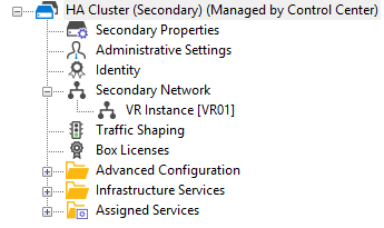
- On your Control Center, go to CONFIGURATION > Configuration Tree > Multi-Range > your range > your cluster > Boxes > your primary firewall > Network > VR Instance [ your virtual instance ].
- In the left menu bar, select IP Configuration.
- Click Lock.
- Click + to assign the first IP address to the first interface, e.g., eth2 =
192.168.0.254. - The IPv4 Addresses window is displayed.
- Enter the name for the first IP address to interface assignment, e.g.,
VRF-to-CLASSROOM1. - Enter the IPv4 Address Configuration
- Interface Name – eth2
- IP Address – Enter the private network address, e.g.,
192.168.0.254. - Responds to Ping – yes.
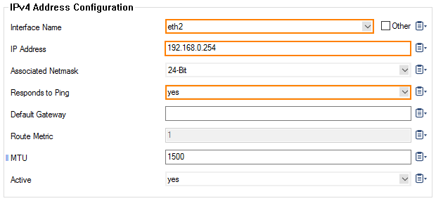
- Click OK.
- Click + to assign the second IP address to the first interface, e.g., eth3 = 62.99.0.33.
- The IPv4 Addresses window is displayed.
- Enter the name for the second IP address to interface assignment, e.g.,
VRF-to-INTERNET. - Enter the IPv4 Address Configuration
- Interface Name – eth3
- IP Address – Enter the private network address, e.g.
62.99.0.33. - Responds to Ping – yes.
- Default Gateway – Enter the IP address for the Internet gateway, e.g.,
62.99.0.254.
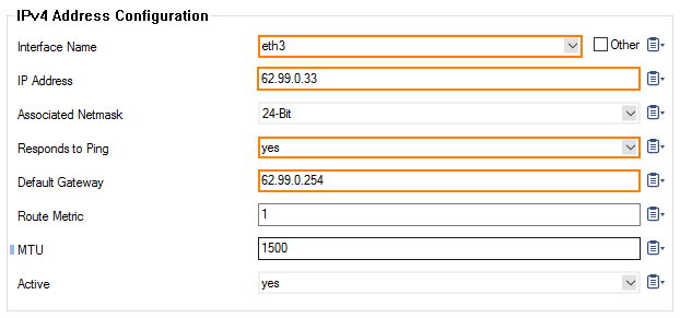
- Click OK.
- Click Send Changes.
- The Activate Changes window opens.
- Click Activate.
Step 5. Verify Your Configuration on Both HA Partners
On the primary firewall, go to CONTROL > Network and click VR01. In case the primary firewall is the active one, the interfaces with its IP addresses are displayed as configured.
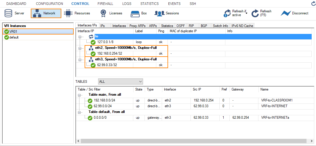
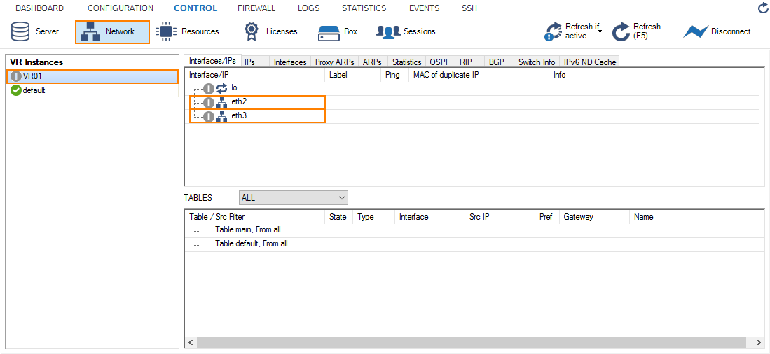
On the secondary firewall, go to CONTROL > Network. In case the secondary firewall is the passive one, the VR01 instance is displayed in gray with the assigned IP addresses being invisible.
To activate the reverse HA constellation, perform an HA failover. For more information, see How to Perform a Manual High Availability Failover. The upper two images will then be displayed with reversed configuration information accordingly .
Step 6. Create an Access Rule for the Newly Created Virtual Router VR01
To pass traffic from interface eth2 (192.168.0.254/32) to eth3 (62.99.0.29/32), create an access rule and constrain the access rule to the virtual router VR01.
- On your Control Center, go to CONFIGURATION > Configuration Tree > Multi-Range > your range > your cluster > Boxes > your primary firewall > Assigned Services > NGFW (Firewall) > Forwarding Rules.
- Click Lock.
- Click + to add an access rule.
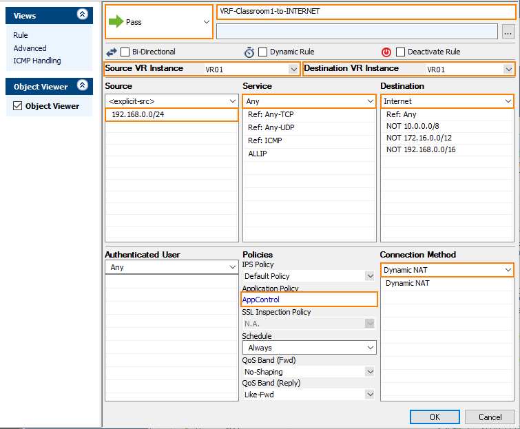
- For the access rule type, select Pass.
- Enter a name for the access rule. To differentiate between rules that apply to the default router instance, and for a clearer overview, it is recommended to prepend a prefix like 'VRF' or 'VR01' to the name of the access rule, e.g.,
VRF-Classroom-to-INTERNET. - Source VR Instance – Select the name of the virtual router instance, e.g. VR01.
- Destination VR Instance – Select the name of the virtual router instance, e.g. VR01.
- Source – Enter the IP address of the source network, e.g.,
192.168.0.0/24. - Service – Select Any.
- Destination – Enter the IP address for the Internet from the list.
- Application Policy – In case you have licensed Application Control, you can activate it now.
- Connection Method – Select Dynamic NAT.
- Click OK.
- Click Send Changes.
- Click Activate.
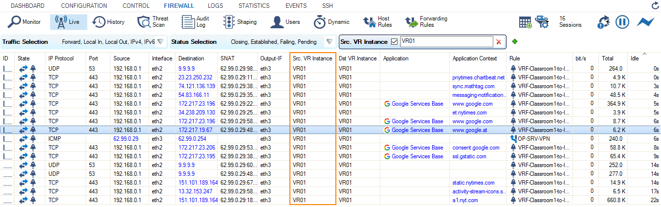
Step 7. Activate Columns to Display the Traffic Flow Through Your Virtual Router Instance
- On your primary firewall, go to FIREWALL > Live.
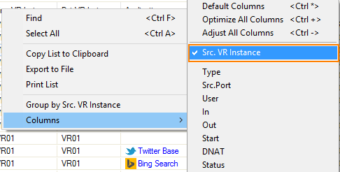
- Right-click on any of the column identifiers of the Live view.
- From the menu, select Columns -> Src. VR Instance.
- Right-click on any of the column identifiers of the Live view.
- From the menu, select Columns -> Dst. VR Instance.
Step 8. Verify that Traffic is Flowing from the Source Network to the Internet
Set up a client with an IP address in the source network (e.g., 192.168.0.1), and set the default route on the client to the address of the virtual router, e.g., 192.168.0.254.
- On your client, open a web browser and go to a website of your choice, e.g., www.nytimes.com
- On your primary firewall, go to FIREWALL > Live.
- The Live view will display a mixture of traffic flowing both through the default router and the virtual router you configured before, e.g.,
VR01.
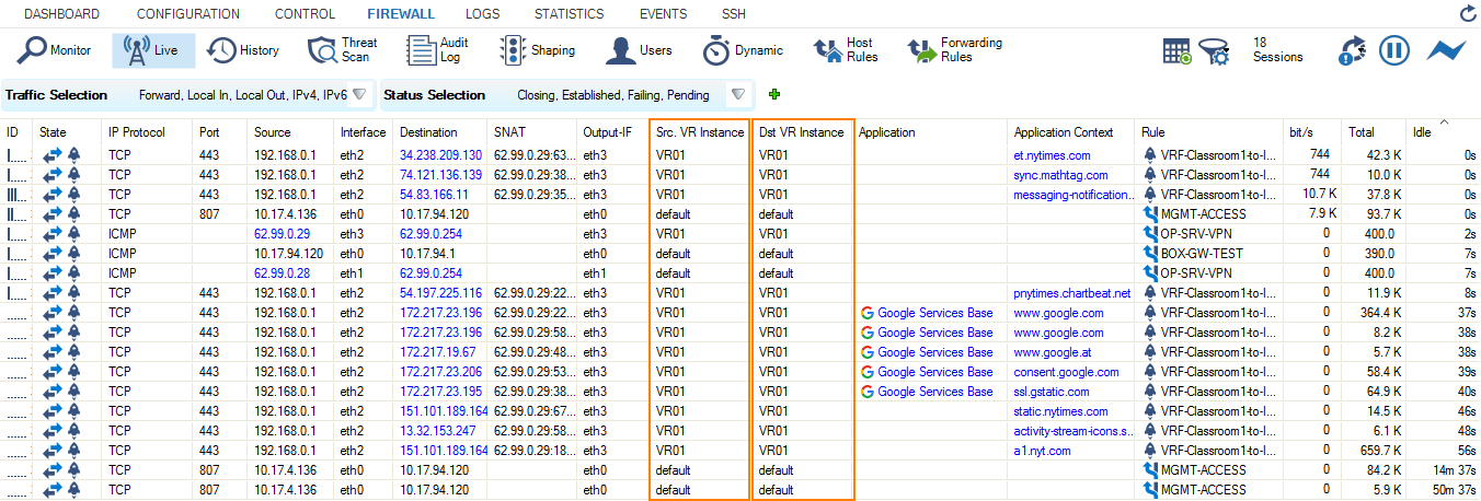
- In order to restrict display output only to the URL you entered before, activate a display filter for the virtual router instance by clicking on the filter symbol in any of the lines showing VR01.