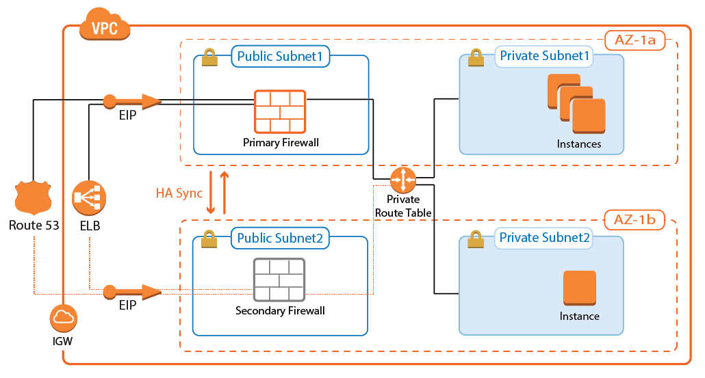
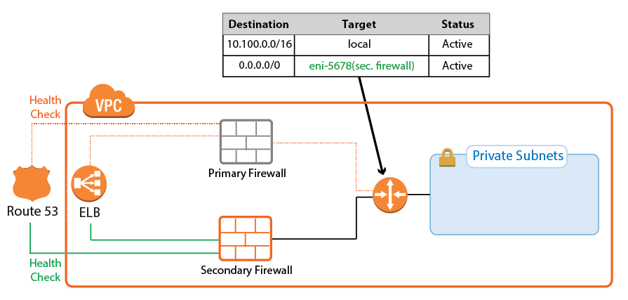
To build highly available services in AWS, each layer of your architecture should be redundant over multiple Availability Zones. Each AWS region is made up of at least two isolated Availability Zones. In case one Availability Zone goes down, your application continues to run in the other datacenter without interruption or even minimal failover time. For the Barracuda CloudGen Firewall, this means deploying two firewall instances to two public subnets, each in a different Availability Zone. The firewalls are in an active-passive cluster. All services, such as the Forwarding Firewall or the VPN, are mirrored to the secondary firewall. Should the primary firewall become unavailable, all services are immediately activated on the secondary firewall. T he now-active secondary firewall connects to the underlying cloud platform and rewrites the routes in the AWS route table to use the now-active firewall as the gateway device for the backend instances. After the route table is rewritten, normal operations are resumed, even if one of the two Availability Zones is experiencing an outage. Failing over from the primary firewall to the second firewall, although fast, is not transparent to the user. Existing connections will time out.
High Availability Clusters must be sized for the expected peak load. If the expected workload is dynamic in nature and a default gateway is not required, use a CloudGen Firewall Auto Scaling cluster instead.
Use Cases for a CloudGen Firewall High Availability Cluster
Site-to-Site VPN – One-way, on-premises to AWS, TINA, and IPsec site-to-site VPN tunnels.
Edge Firewall – Scan for malicious traffic using the built-in IPS and handle access to resources via access rules.
Secure Remote Access – Client-to-site VPN, CudaLaunch, and SSL VPN using TINA, SSL VPN, and IPsec VPN protocols.
Deploying a High Availability Firewall Cluster via CloudFormation Template
It is recommended to deploy the High Availability Cluster via a CloudFormation template. The template deploys two firewalls that are automatically joined into the High Availability Cluster in the public subnets. The route table associated with the private subnets is configured to use the active firewall as the outbound gateway.
Create an IAM role for the firewall cluster. For step-by-step instructions, see How to Create an IAM Role for a CloudGen Firewall in AWS.
Download the CGF_HA_floatingEIP.json template and parameter file from the Barracuda Network GitHub account: https://github.com/barracudanetworks/ngf-aws-templates/tree/master/HA Cluster.
Accept the Software Terms for the Barracuda CloudGen Firewall PAYG or BYOL image in the AWS Marketplace.
Create a parameter template file containing your parameters values.
Deploy the CGF_HA_floatingEIP.json CloudFormation template via AWS CLI or AWS console.
aws cloudformation create-stack --stack-name "YOUR_STACK_NAME" --template-body YOUR_S3_BUCKET/CGF_HA_floatingEIP.json --parameter YOUR_S3_BUCKET/CGF_HA_floatingEIP.json
During deployment, the following resources are created by the template:
Two public and two private subnets in a VPC. The subnets are spread out over multiple Availability Zones.
Two CloudGen Firewall (PAYG or BYOL) instances joined together into a High Availability Cluster.
For step-by-step instructions on how to deploy a CloudFormation template, see How to Deploy a CloudGen Firewall in AWS via CloudFormation Template.
Addendum: Manual Setup for Automatic Failover in AWS
The CloudFormation template includes several custom settings and post-deployment tasks that will ensure that a high-availability cluster can work as-is on new deployments.
This includes scripts to automatically transfer the Elastic IP to the active firewall and monitor it for unexpected changes, reverting it to the correct system when necessary.
In cases where the template cannot be utilized (e.g., when a manual deployment via the AWS console is performed, or a secondary system is added to an existing one), these tasks must be performed manually.
The relevant reference scripts can be downloaded from Barracuda Networks GitHub and must be modified before implementation.
This Reference Architecture presumes the use of a single static Elastic IP that will be moved between the respectively active firewall. Alternatives such as Route 53 DNS shifting or a Network Load Balancer use health probes and do not require these scripts.
Step 1: Public IPs
Both firewalls require a public IP, but it does not need to be a static address. We will instead make use of automatically assigned public IPs.
Ensure that “auto-assign public IP” is enabled. This is only the case for default VPCs; custom ones must have the option set on the public firewall subnet.
Existing instances will not inherit this change, if it was disabled. These must be redeployed.
Step 2: Collect Information
To allow proper operation, the scripts must be aligned to your environment. The following details are necessary for that purpose:
Instance ID of primary firewall.
Instance ID of secondary firewall.
Address of the Elastic IP.
Allocation ID of the Elastic IP.
Step 3: Prepare Scripts
Download the 4 files:
https://github.com/barracudanetworks/ngf-aws-templates/tree/master/HA Cluster/Manual Setup
aws-shift-eip.shfor the primary firewallaws-shift-eip.shfor the secondary firewallxcloud-aws-check-eip-assoc.shaws-check-eip-assoc
Open the two
aws-shift-eip.shfiles in a text editor.Replace $IID with the respective instance ID of the primary and secondary firewall.
Replace $EID with the allocation ID of the Elastic IP.
These two scripts are almost identical, differing only in the necessary instance ID and the generated log line.Open
aws-check-eip-associn a text editor.Replace $ELASTICIP with the public address of the Elastic IP.
This is a configuration file for the system scheduler that calls the monitoring script.
Step 4: Upload Scripts
Upload the respective
aws-shift-eip.shand the other two files to both boxes.Make the scripts (the .sh files) executable
chmod +x aws-shift-eip.shchmod +x xcloud-aws-check-eip-assoc.sh
Move files to correct directories:
mv aws-shift-eip.sh /opt/phion/hooks/hamv xcloud-aws-check-eip-assoc.sh /opt/phion/binmv aws-check-eip-assoc /etc/cron.d/
Restart the system scheduler:
systemctl restart crond
The regular system scheduler calls will be logged in box > System > cron.
If a failover occurs and the IP is shifted, it will be logged into box > Cloud > control.
(Alternative) Deploying a High Availability Firewall Cluster via AWS Console
To deploy a CloudGen Firewall High Availability Cluster via AWS Console, follow these basic steps:
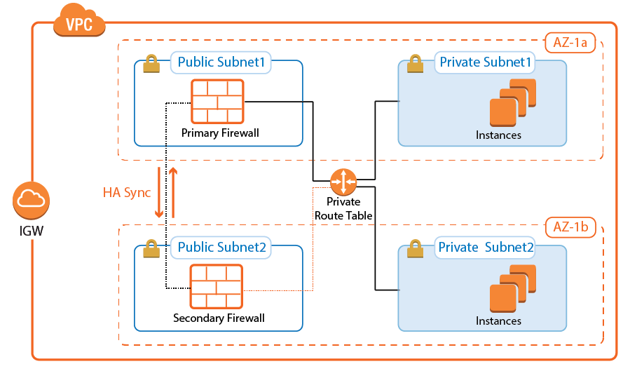
Create an IAM role for your firewall instances.
Create a VPC and add two public and private subnets in two Availability Zones.
Attach an Internet gateway and associate one route table with the public subnets, the second with the private subnets.
Launch one firewall instance into each public subnet. Both firewalls require public IP addresses.
Disable the source/destination check for each firewall.
Add routes to the route table to allow the public subnets Internet access and the private subnets to route over the active firewall instance.
Join the two firewalls into an High Availability Cluster.
Add an Elastic Load Balancer or configure Route 53.
For step-by-step instructions, see How to Configure a Multi-AZ High Availability Cluster in AWS Using the AWS Console and How to Set Up a High Availability Cluster.
Cloud Integration for Route Shifting
Cloud Integration allows the firewall instance to authenticate to the underlying cloud platform by using API calls. The required Azure IAM role for authentication will be supplied during deployment. Cloud Integration is used to populate the Cloud Information element in the Barracuda Firewall Admin dashboard and, more importantly, to rewrite AWS route tables. Rewriting the VPC route tables is necessary every time the second firewall has to takeover. During the failover, the now-active firewall rewrites the target of every route to use the active firewall running the services. This works for all route tables in the VPC. The active firewall continues to poll the route tables to ensure that the active firewall is always used.
Primary Firewall Active
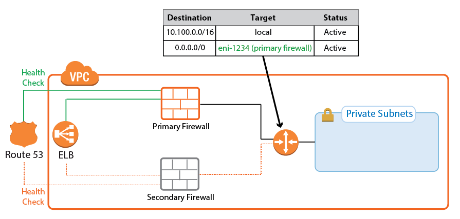
Secondary Firewall Active
On the firewall, go to CONTROL > Network > AWS Routes. All the route tables for the VPC are listed. Routes that use one of the firewalls are shown with a green icon. During takeover, the icon temporary turns red to indicate that a failover is in progress. After the route table rewrite, the network interface ID (eni-123456) matches the now-active firewall.

For step-by-step instructions, see Cloud Integration for AWS.
Single Endpoint for Incoming Traffic: Route 53 or Elastic Load Balancer
Using two public IP addresses for the active-passive High Availability Cluster may not always be possible. To use a single FQDN that always sends traffic over the active firewall, you can use either a classic Elastic Load Balancer or Route 53. Both services are similar in that they use health checks and send traffic to the healthy destination. For TCP-only services, either service can be used. For UDP-based services, such as IPsec, use Route 53.
Classic Elastic Load Balancer
The classic Elastic Load Balancer is a managed layer-4 TCP load balancer. The load balancer can only be addressed by the DNS name associated with it. It is not possible to work with the IP address the hostname resolves to directly because the underlying load balancing instances may change at any time.
The Elastic Load Balancer is responsible for distributing traffic to all healthy instances it is associated to. To make sure that traffic is sent only to the active firewall, define the health check for a service. For example, use TCP:691 as the health check target if a VPN service is running on the firewall. The load balancer continuously polls the VPN service and considers the instance healthy if the TCP connection succeeds. Since the firewall services are running only on the active firewall, the health check always fails for the passive firewall. The passive firewall is considered unhealthy, and no traffic is forwarded to this instance by the load balancer.
Traffic passing through an Elastic Load Balancer rewrites the source IP address to that of the load balancer instance. If your application requires the public IP address of the client, use Route 53 instead.
For step-by-step instructions, see How to Configure an Elastic Load Balancer for CloudGen Firewalls in AWS.
Route 53
Route 53 is an authoritative DNS service by AWS. Route 53 allows you to monitor endpoints and change the returned record set according to the state of the health check. Create a health check for a service running on the primary firewall of your High Availability Cluster. Create two record sets using a failover routing policy and attach the health check to the primary firewall. No distinct health check is created for the secondary firewall. If everything fails, it is better to attempt to reach at least one firewall in the cluster than to return nothing at all. The secondary firewall is also a better choice as a fail-safe because the default behavior of a High Availability Cluster favors the secondary firewall. For example, if both the primary and secondary firewall start the services at the same time, the secondary firewall continues to run while the primary firewall shuts the services down.
For step-by-step instructions, see How to Configure Route 53 for CloudGen Firewalls in AWS.
Control Center-Managed CloudGen Firewall High Availability Cluster
The Barracuda Firewall Control Center is a central management appliance for the CloudGen Firewall that can be deployed as a virtual appliance on-premises or in the cloud. Managing the High Availability Cluster with a Barracuda Firewall Control Center separates the firewall configuration and monitoring from deployment and integration with other AWS services. This is especially useful for highly specialized or large departments with dedicated network security teams and multiple developer teams using automatic deployments. Managed firewalls are preconfigured on the Control Center. During provisioning of the firewall instance, the firewall configuration and, optionally, licenses are automatically retrieved from the Control Center. To use BYOL licenses, pool licenses bound to the Control Center are used instead of single BYOL licenses bound to the EC2 instance of the firewall. Pool licenses are available in multiples of 5.
For step-by-step instructions, see How to Modify CloudFormation Templates to Retrieve the PAR File from a Control Center.
For more information, see Firewall Control Center and Central Management.
Create Access Rules
By default, the Forwarding Firewall service blocks all traffic. To allow traffic through the firewall, you must create access rules with an allow action, such as Pass or Dst NAT. When creating the rules, make sure you create them so they will match the same type of traffic independent of which firewall is running the services on. For Dst NAT and App Redirect rules, enter both the management IP address of the primary and secondary firewalls, or use the All Firewall IPs.
For step-by-step instructions, see Access Rules.
Internet to Backend Services Using the Firewall as the Default Gateway
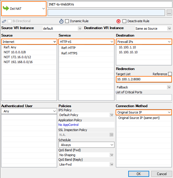
Create the following access rule to forward traffic from the Internet to an internal web server, where the web server uses the firewall as the default gateway.

Action – Select Dst NAT.
Source – Select the source depending on how traffic is routed to the firewall:
Through an ELB – Select Any or the network object containing the networks the ELB is deployed in.
Through Route 53 / Elastic IP – Select Internet.
Destination – Select a network object containing the two static IP addresses of the firewalls.
Connection Method – Select Original Source IP.
Redirection Target – Enter the IP address of the backend service. Optionally, append the port number to redirect to a different port. E.g,
10.100.1.2or10.100.1.2:8080
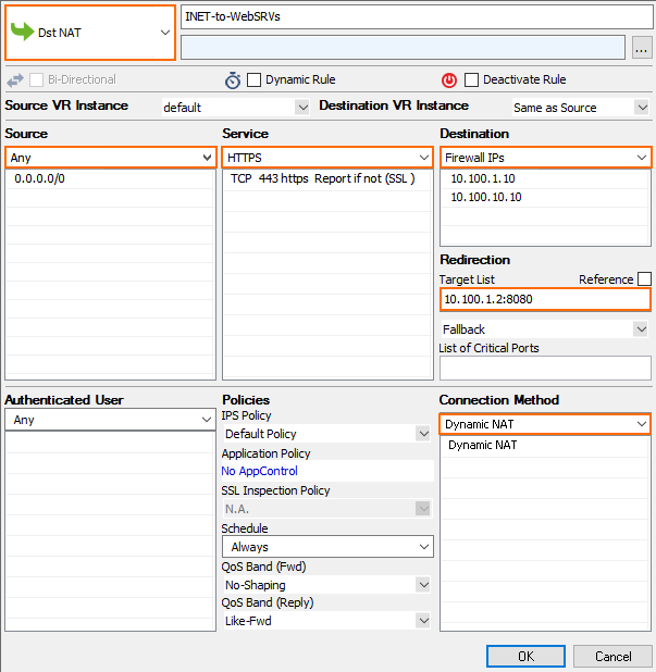
Internet to Backend Services not Using the Firewall as the Default Gateway
Create the following access rule to forward traffic from the Internet to an internal web server.

Action – Select Dst NAT.
Source – Select the source depending on how traffic is routed to the firewall:
Through an ELB – Select Any or the network object containing the networks the ELB is deployed in.
Through Route 53 / Elastic IP – Select Internet.
Service – Select the service. E.g., HTTP+S.
Destination – Select a network object containing the two static IP addresses of the firewalls.
Connection Method – Select Dynamic NAT.
Redirection Target – Enter the IP address of the backend service. Optionally, append the port number to redirect to a different port. E.g,
10.100.1.2or10.100.1.2:8080
