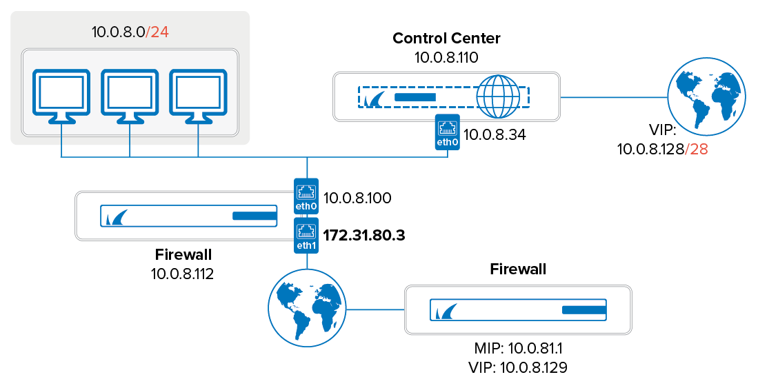
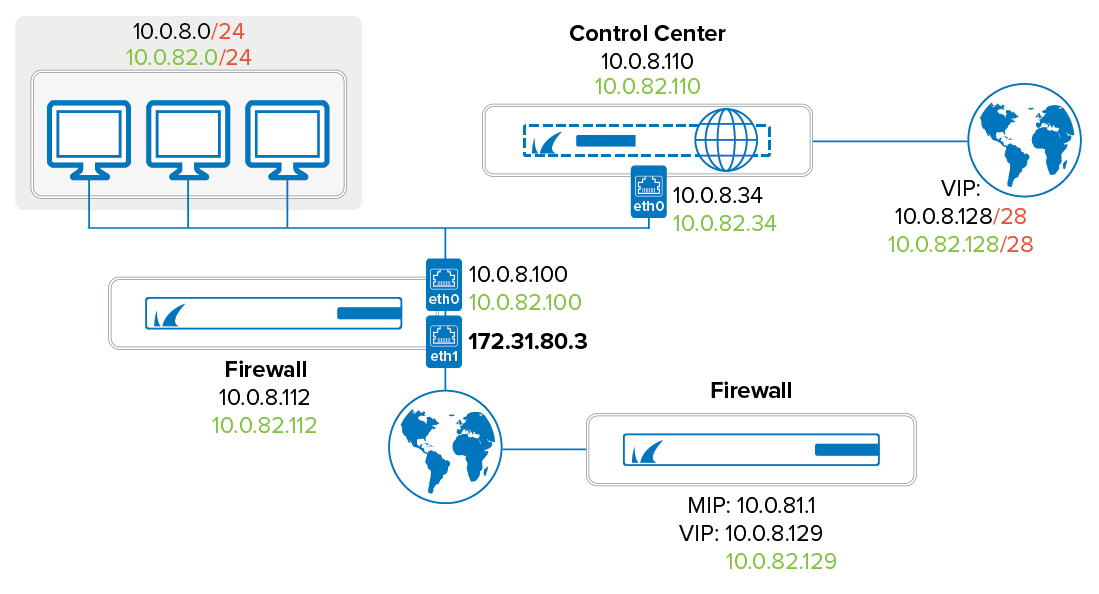
In this example, a Barracuda Firewall Control Center is migrated to a new network segment. In the example network, the Control Center is to be moved from 10.0.8.0/24 to 10.0.82.0/24. (Note: It is assumed that the external IP address of the HQ border firewall (eth1: 172.31.80.3) remains unaffected.)
The following network diagrams give an overview of the initial and the planned network configuration:
Initial network situation: | Network after CC migration: |
Preparing the Network for CC Migration to a New Network
The following preliminary steps must be taken before actual migration of the Barracuda Firewall Control Center (CC).
Step 1. Introduce a New Box IP
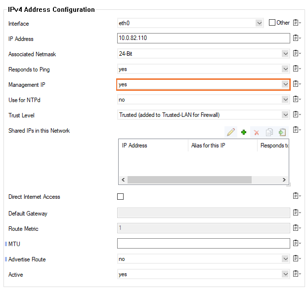
Introduce an additional Box IP at 10.0.8.110 on the CC Syslog Service into the Control Center on box level. To do so, navigate to CONFIGURATION > Configuration Tree > Box > Network > IP Configuration > Additional Local IPs. In the example, the new IP introduced is the address 10.0.82.110.
Additional Networks configuration dialog:

Step 2. Introduce a Second Server IP on the CC Box (Server Configuration)
Go to CONFIGURATION > Configuration Tree > Box > Virtual Servers > S1 > Server Properties.
Enter the IP address
10.0.82.34into the Second-IP or Additional IP field.
Step 3. Activate the New Network Configuration
Go to CONTROL > Box and click the Activate New Network Configuration link accessible via the menu on the left (Network).
Step 4. Introduce Additional Management IPs
Log into the Control Center on server level using the CC tab and the CC IP 10.0.8.34.
Go to CONFIGURATION > Configuration Tree > Multi-Range > Global Settings > CC Identity.
Insert the IP addresses
10.0.82.34and10.0.82.110into the field Additional CC IP Addresses.
Step 5. Introduce New Box VIP Ranges
While you are still logged on at CC level, browse to CONFIGURATION > Configuration Tree > Multi-Range > Global Settings > Box VIP Network Ranges.
Introduce the net
10.0.82.128/28as a new VIP Network.
Box VIP Network Ranges:

Step 6. Adapt Routing on the Firewall
Open the network configuration of the corresponding firewall via the configuration tree of the CC.
Configure the Routing to the new LAN (
10.0.82.0/24).Click Send Changes and Activate.
Step 7. Introduce the Additional Server IP on the Firewall (FW)
On the Barracuda CloudGen Firewall employing the firewall, browse to CONFIGURATION > Configuration Tree > Box > Virtual Servers > your virtual server > Server Properties.
In the Virtual Server IP Addresses section, add the IP address
10.0.82.100to the Additional IP table.
Step 8. Introduce Additional FW Rule Sets on the HQ Border Firewall
Only rules concerning the redirection of the remote management tunnels need to be adapted.
Clone the needed existing rulesets, and perform the necessary changes on the clones.
Step 9 - Ensure Correct Routing
Ensure correct routing from the remote boxes to the Control Center.
Step 10. Ensure External Management Access
To maintain connectivity when changing the VIP or in case of a remote management settings misconfiguration, make sure to configure management accesses to all boxes that work independently of the management VPN tunnels (for example, define external management IPs on all boxes of the branch offices).
Step 11. Activate the New Network Configuration
Log into the Control Center on box level.
Go to CONTROL > Box.
Click Activate New Network Configuration.
Migrating the CC to a New Network
To relocate the CC to its new environment, proceed as follows:
Step 1. Check Configuration Updates for Successful Completion
Log into the Control Center on server level using the CC tab and the new CC IP 10.0.82.34.
Go to CONTROL > Configuration Updates.
Check the update status messages in the list for all boxes bound to the Control Center.
Do NOT proceed with the following steps unless all updates have been completed successfully.
Step 2. Reconfigure Remote Managed Boxes
Go to CONFIGURATION > Configuration Tree > Multi-Range > your range > your cluster > your box > Network.
In the left menu, select Management Access.
In the Remote Management Tunnel section, change the following network parameters:
Virtual IP (VIP): Switch the Virtual IP from 10.0.8.129 to 10.0.82.129.
Tunnel Details: Switch the Target Networks from 10.0.8.0/24 to 10.0.82.0/24. Switch the Reachable IPs from Server IP 10.0.8.34 to 10.0.82.34 and MIP 10.0.8.110 to 10.0.82.110.
Step 3. Activate the New Network Configuration on the Boxes
Go to CONTROL > Box Execution.
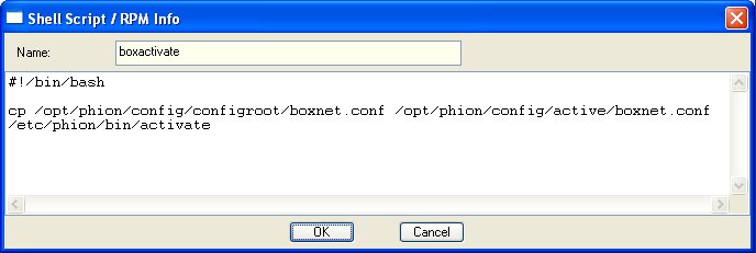
Click New Script to generate a script for activation of the new network configuration on all boxes.
boxactivate shell script for box network activation:

Name the script for example
boxactivate. Add the following lines to it:
#!/bin/bash
cp /opt/phion/config/configroot/boxnet.conf
/opt/phion/config/active/boxnet.conf
/etc/phion/bin/activate
Execute the script by selecting it in the Scripts tab and simultaneous selection of the boxes where it is to be executed in the window left to the Scripts tab.
While all needed objects are selected, click the Create Task button in the Selected Boxes section. The script is now executed.
Step 4. Check Configuration Updates for Successful Completion
Go to CONTROL > Configuration Updates and check the update status messages for successful completion of box network activation.
Step 5. Set the New CC IPs
To assure that the correct CC IP address is used for communication, interchange the Management IPs created above in Step 4 - Introduce additional Management IPs (see above).
Switch the CC IPs 10.0.8.34 and 10.0.8.110 with the additional CC IPs 10.0.82.34 and 10.0.82.110 respectively.
Step 6. Delete Obsolete Rule Sets on the HQ Border Firewall
Delete the former rulesets on the HQ border firewall that have been replaced through introduction of additional sets bound to the new IPs in Step 8 - Introduce additional FW rule sets on the HQ border firewall (see above).
Step 7. Assert the New Network Configuration
Log into the Control Center on box level using the Box tab and the MIP 10.0.82.110.
Go to CONTROL > Box and click the Activate New Network Configuration link.
Select Soft activation from the available options.
Step 8. Perform a Complete Update via the Control Center
Log into the Control Center on server level using the CC tab and the CC IP 10.0.82.34.
Browse to CONTROL > Configuration Updates tab.
Click Update Now.

