To dynamically learn OSPF-propagated routes from a remote location connected via TINA VPN tunnel, VPN next hop interfaces are used to create an intermediary network.
You must complete this configuration on both the local and the remote CloudGen Firewalls by using the respective values below:
| Example values for the local firewall | Example values for the remote firewall | |
|---|---|---|
| VPNR Next Hop Interface Index | 1 | 1 |
| VPN Next Hop Interface IP Address | 192.168.20.1/24 | 192.168.20.2/24 |
| Box Shared IP | 192.168.20.1 | 192.168.20.2 |
| VPN Local Networks | empty | empty |
| VPN Remote Networks | empty | empty |
| Router ID | 192.168.20.1 | 192.168.20.2 |
Before You Begin
- A free /24 subnet (e.g.,
192.168.20.0/24) for the intermediary network is required.
Step 1. Add a VPN Next Hop Interface
Add a VPN next hop interface using a /24 subnet (e.g., 192.168.20.0/24).
- Go to CONFIGURATION > Configuration Tree > Box > Assigned Services > VPN-Service > VPN Settings.
- Click Lock.
- In the left menu, select Routed VPN.
- Next to the Next Hop Interface Configuration table, click Add.
- In the VPN Interface Properties window, configure the following settings and then click OK.
- In the VPN Interface Index field, enter a number between
0and999. E.g.,11 - In the IP Addresses field, enter the VPN interface IP address including the subnet. E.g.,
192.168.20.1/24for the local CloudGen Firewall, or192.168.20.2/24for the remote firewall. - In the Multicast Addresses field, enter the OSPF multicast addresses:
224.0.0.5 224.0.0.6
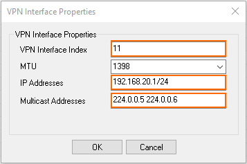
- Click OK. The interface is now listed in the Next Hop Interface Configuration table.

- In the VPN Interface Index field, enter a number between
- Click Send Changes and Activate.
Step 2. Add the VPN Next Hop Interface IP Address to the Firewall Listening IP Addresses
Introduce the IP address of the VPN next hop interface on the firewall.
- Go to CONFIGURATION > Configuration Tree > Box > Network.
- In the left menu, select IP Configuration.
- Click Lock.
- In the Shared Networks and IPs section, click +. The Shared Network and IPs window opens.
- Select the virtual Interface.
- In the Network Address field, enter the network the virtual interface resides in.
- In the Shared IPs in this Network table, click + and add the IP address of the VPN next hop interface.
- Click OK.
- Click Send Changes and Activate.
Step 3. Configure the TINA Site-to-Site VPN Tunnels
You can configure the VPN tunnel using the GTI Editor for managed CloudGen Firewalls, or using the Site-to-Site configuration dialog if you are using standalone CloudGen Firewalls.
In the GTI Editor
Edit the VPN tunnel to remove the local and remote networks and add the VPN next hop interface ID.
- Go to the global/range/cluster GTI Editor.
- Click Lock.
- Click on the VPN tunnel, and click on the first Transport to edit the VPN tunnel configuration. For more information, see How to Create a VPN Tunnel with the VPN GTI Editor.
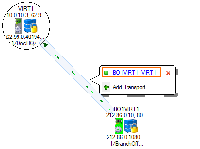
- Remove all Local Networks from the remote and local VPN services.
- Enter the VPN next hop interface ID for the remote and local VPN services. E.g.,
11
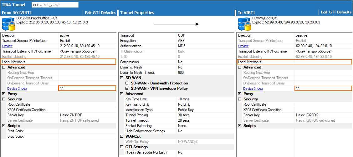
- Click OK.
- Click Send Changes and Activate.
Standalone CloudGen Firewalls
On both the remote and local firewalls, configure a TINA VPN tunnel with the VPN Interface Index. Leave the local and remote networks empty.
- Log into the local CloudGen Firewall.
- Go to CONFIGURATION > Configuration Tree > Box > Assigned Services > VPN-Service > Site to Site.
- Click Lock.
- Right-click in the TINA Tunnels tab and select New TINA tunnel. The TINA tunnel window opens.
- Enter a Name.
Configure the Transport, Encryption and Authentication settings as well as the Local and Remote public IP addresses. For more information, see How to Create a TINA VPN Tunnel between CloudGen Firewalls.
- Exchange the Peer Identification keys.
In the Remote Networks tab, enter the VPN Interface Index number that you created in the VPN Interface Configuration in step 1. E.g.
11
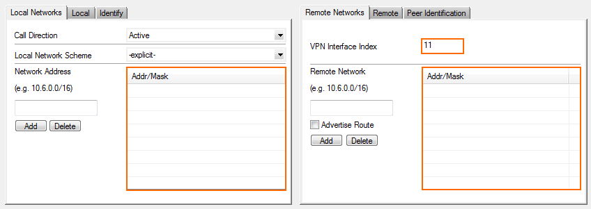
- Click OK.
- Click Send Changes and Activate.
Step 4. Configure the OSPF Service
The OSPF setup must be completed on both the local and remote firewalls. The configuration steps and values are the same except for the Router ID and propagated networks.
Step 4.1 Configure which Routes to Propagate into OSPF
Select the routes you want to propagate.
- Go to CONFIGURATION > Configuration Tree > Box > Network.
- Click Lock.
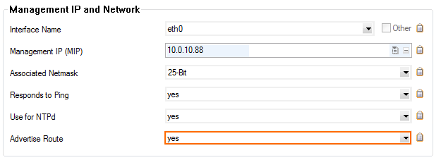
- To propagate the management network, set Advertise Route to yes in the Management IP and Network section.
- In the left menu, click on Routing.
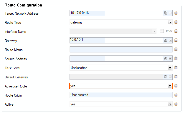
- Double-click on the direct attached and gateway routes you want to propagate. The Routes window opens.
- Set Advertise Route to yes and click OK.
- Click Send Changes and Activate.
Step 4.2 Configure the OSPF Router
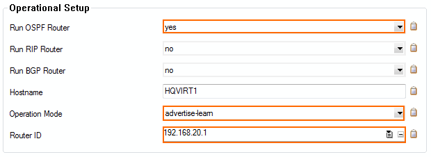
Enable OSPF and use the VPN Next Hop interface IP address as the Router ID.
- Go to CONFIGURATION > Configuration Tree > Box > Assigned Services > OSPF-RIP-BGP-Service > OSPF/RIP/BGP Settings.
- Click Lock.
- Set Run OSPF Router to Yes.
- Set Operation Mode to advertise-learn.
- Enter the Router ID. Typically the VPN next hop interface IP address is used. E.g.,
192.168.20.1for the local CloudGen Firewall, or192.168.20.2for the remote firewall.
- In the left menu, click OSPF Router Setup.
- Select Cisco Type from the ABR Type drop-down.
Enter the Terminal Password. Use this password if you must directly connect to the dynamic routing daemon via command line for debugging purposes.
- Click Send Changes and Activate.
Step 4.3. Create an OSPF Area Setup
- Go to CONFIGURATION > Configuration Tree > Box > Assigned Services > OSPF-RIP-BGP-Service > OSPF/RIP/BGP Settings.
- Click Lock.
- In the left menu click OSPF Area Setup.
- In the OSPF Area Configuration, click + to add Areas.
- Enter the OSPF area Name.
- Click OK. The Areas window opens.
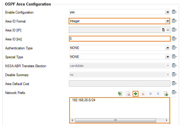
- From the Area ID Format dropdown, select Integer.
- Enter the Area ID[Int]. E.g.,
0 - If authentication is selected in the Parameter Template select the Authentication Type.
- Click + add the VPN next hop interface network to the Network Prefix table: E..g,
192.168.20.0/24
- Click OK.
- Click Send Changes and Activate.
Step 6. Verify the OSPF Service Configuration
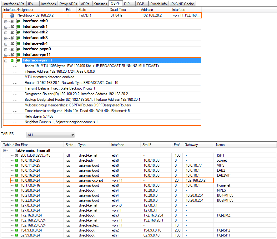
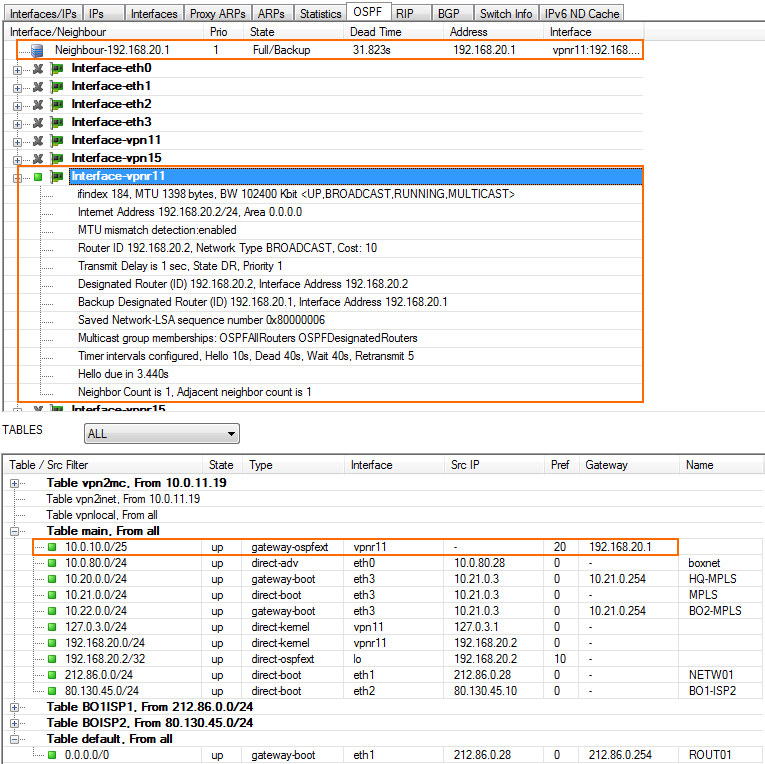
On the CONTROL > Network page, verify that OSPF is active on the VPN next hop interface and that the remote CloudGen Firewall is listed as an OSPF neighbor. The routes learned via OSPF are listed with a type of gateway-ospf in the routing table. The Interface is the VPN next hop interface and the Gateway the IP address of the remote VPN next hop interface IP address.
Local Firewall CONTROL > Network > OSPF page:
Remote Firewall CONTROL > Network > OSPF page:
Step 6. Create Access Rules for VPN Traffic
Create access rules on both local and remote firewalls to allow traffic from the learned networks through the VPN tunnel. For more information, see How to Create Access Rules for Site-to-Site VPN Access.
