Redundant VPN tunnels help maintain constant connectivity between Barracuda CloudGen Firewalls, for example, at headquarters and branch offices. They help minimize the impact of hardware crashes and interruptions to Internet connections, increasing the stability and reliability of VPN tunnels over the Internet. They can also help eliminate the need to upgrade the existing infrastructure (frame relay, dedicated line) when the load exceeds the limits but upgrading is out of the question due to high costs. In this setup, specific types of traffic can be redirected to specific tunnels as determined by service objects in the firewall rule that handles the traffic. In this way, response-critical traffic (e.g., SSH, Telnet, Citrix, etc.) can be directed to the tunnel using a dedicated line/frame relay (usually offering shorter delay times), while bulk traffic (e.g., SQL server replication, Lotus Notes replication, etc.) can be directed to the Internet tunnel. However, all traffic appears to use the original source IP address, regardless of the tunnel and the direction used.
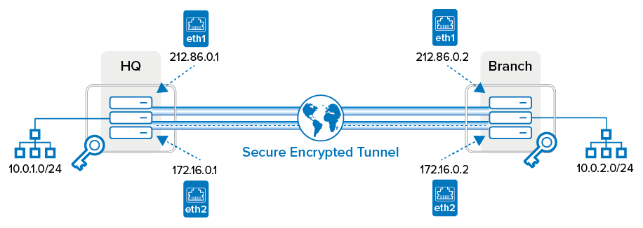
This article provides a diagram that illustrates an environment using this setup and example settings to create the site-to-site TINA VPN tunnels for this environment. After configuring the VPN tunnels, you must also configure the network routes.
The following figure illustrates a redundant VPN tunnel setup with two links on each side of the tunnel. This setup results in four possible ways to build up the tunnel enveloping connection. The algorithm determining the succession of retries works as follows:
- First local IP to first peer IP
- First local IP to second peer IP
- Second local IP to first peer IP
- Second local IP to second peer IP

If the preferred tunnel enveloping connection fails to be established, it cannot be rebuilt automatically. The tunnel must be terminated manually. It is then immediately rebuilt with the specified algorithm. The setup depicted in the above example uses the following settings:
| Tunnel 1 - 2 | Peer IP Address | Local Bind IP Address |
|---|---|---|
| HQ | 212.86.0.2 | 212.86.0.1 |
| Branch | 212.86.0.1 | 212.86.0.2 |
Step 1: Create the VPN Tunnels
First, create the site-to-site TINA VPN tunnels for the HQ and branch offices. For the example environment, the following settings are used:
| HQ | ||
| Tab | Setting | Values |
|---|---|---|
| Local Networks | Call Direction | Passive |
| Network Address | 10.0.1.0/24 | |
| Local | IP Address or Interface used for Tunnel Address | 172.16.0.1, |
| Remote Networks | Remote Network | 10.0.2.0/24 |
| Remote | Remote Peer IP Addresses | 172.16.0.2, |
| Branch | ||
| Tab | Setting | Values |
|---|---|---|
| Local Networks | Call Direction | Active |
| Network Address | 10.0.2.0/24 | |
| Local | IP Address or Interface used for Tunnel Address | 172.16.0.2, |
| Remote Networks | Remote Network | 10.0.1.0/24 |
| Remote | Remote Peer IP Addresses | 172.16.0.1, |
Step 2: Configure the Direct Routes
After you create the TINA VPN tunnels, configure the direct routes for the HQ and branch offices. Because this setup uses redundant VPN tunnels, the direct routes on the HQ and branch systems use the same settings. For the example environment, the following settings are used:
| Setting | 1 | 2 |
|---|---|---|
Target Network | 212.86.0.0/24 | 172.16.0.0/24 |
Route Type | directly attached network | directly attached network |
| Interface Name | eth1 | eth2 |
When one of the VPN tunnels is established successfully, the network routes are introduced by the system itself. To view these routes, go to the Control > Network page.
