Use a local bridge to transparently connect your local workstation with the network across a Barracuda CloudGen Firewall. This configuration allows you to explore the firewall's advanced traffic and application inspection features by using traffic that your workstation generates on the LAN. To make the connection transparent, you must configure a local bridge and create an access rule to allow traffic between the bridged interfaces.


Before You Begin
Before configuring a local bridge, make sure that the following services are correctly configured:
- Firewall – It is assumed that port 1 is the management port and the default management IP 192.168.200.200 listens on this interface.
- Wi-Fi – For CloudGen Firewalls with built-in Wi-Fi, the Country must be selected. Otherwise, IP configurations involving Wi-Fi interfaces are not possible.
- DHCP Server – Make sure that DHCP server and DHCP client are disabled. By default, both are disabled.
These instructions also provide example settings that assume that your workstation is connected to port 1 and that you are creating a bridge between port 2 and port 3.
Step 1. Configure the Local Bridge
- Go to CONFIGURATION > Configuration Tree > Box > Network.
- For CloudGen Firewalls with built-in Wi-Fi:
- Select Wi-Fi from the Configuration menu in the left menu.
- Verify the Location is configured correctly.
- In the left menu, select Layer 2 Bridging.
- Click Lock.
- In the Bridged Interface Group table, add a group:
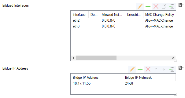
- Bridged Interfaces – In this table, add all of the interfaces that must be bridged together in this group. For example, add entries for port 2 and 3.
For each interface, you can specify the following settings:- Interface – The exact network interface label, as listed in the network configuration. For VLANs, enter the physical VLAN interface and the VLAN tag separated by a dot. For example,
eth1.5. - Allowed Networks (ACL) – Networks that are allowed to communicate over the bridged interface. You can enter complete networks, individual client/server IP addresses, or network ranges. For example, enter
0.0.0.0/0in the configurations for port 2 and port 3. - Unrestricted MACs – List of MAC address for which the Allowed Networks (ACL) does not apply.
- MAC Change Policy – To specify if the MAC address of the interface can be changed, select Allow–MAC–Change (default). If the MAC address must not be changed, select Deny–MAC–Change.
- Interface – The exact network interface label, as listed in the network configuration. For VLANs, enter the physical VLAN interface and the VLAN tag separated by a dot. For example,
- Bridge IP Address – In this table, add an entry or edit an existing entry for the gateway to assign an IP address to this bridging group. In the entry, specify the following settings for the gateway.
- Bridge IP Address – IP address for the gateway. For example, enter
10.17.11.55or an IP address that is relative to your network. Bridge IP Netmask – Netmask for the gateway.

- Bridge IP Address – IP address for the gateway. For example, enter
- Bridged Interfaces – In this table, add all of the interfaces that must be bridged together in this group. For example, add entries for port 2 and 3.
- Click Send Changes and Activate.
- Perform a Failsafe Network Activation (Control > Box).
Step 2. Create an Access Rule for Local Bridging
After configuring the local bridge, you must create an access rule to allow traffic across the bridge and use the advanced traffic inspection features of the firewall.
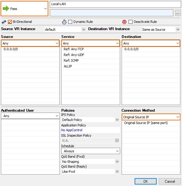
- Create a Pass access rule with the following settings:
- Bi–Directional – Enable
- Source – Select Any
- Service – Select Any
- Destination – Select Any
- Connection Method – Select Original Source IP

- (Optional) Enable Application Control and SSL Inspection. For more information, see Application Control.
- Click OK.
- Click Send Changes and Activate.
