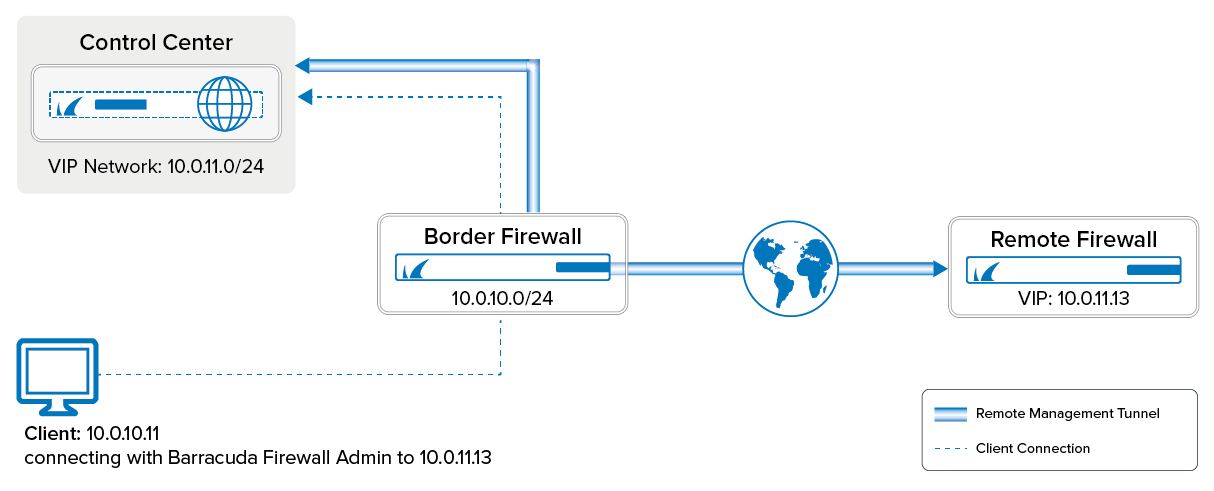
If the managed CloudGen Firewall cannot directly reach the Barracuda Firewall Control Center, it must connect via a remote management tunnel. The remote firewall uses the certificate keys exchanged at deployment to authenticate to the Control Center. Since it is not recommended to use an external IP address as a management IP, the remote firewall is assigned a Virtual IP (VIP) in the local network. The VIP is used to connect to the remote firewall from the local network. Depending on whether the VIP is a subnet of the local network or a separate network, you will need access rule and route entries on the border firewall and an access rule on the CC firewall. If the remote firewall is using a IPv6 IP address to connect, the Control Center must have a global unicast IPv6 address.
Limitations
- Only IPv4 traffic can be sent through the management tunnel.
Before You Begin
- Use an available network or subnet to be used for the VIP addresses.
- (IPv4 only) You need the external IPv4 address of the border firewall.
- (IPv6 only) The Control Center must be reachable through an IPv6 global unicast address.
- Firewalls in a HA cluster must have the public IP address configured on box level.
Step 1. Configure a VIP Network on the Control Center
- Go to CONFIGURATION > Configuration Tree > Multi-Range > Global Settings > VIP Networks.
- In the left menu, select VIP Networks.
- Click Lock.
- In the VIP Networks table, add an entry for the network range. Configure the following settings for the entry:
- Name – A name for the network range.
- Network Address – Enter the VIP network address. E.g.,
10.0.11.0 - Netmask – Select the netmask. E.g., 24-Bit

- (optional) In the left menu, click VPN Settings.
(optional) The VPN Settings are set to sensible default values. If necessary, you can change these settings:
(optional) In the left menu, click on Rekey/Alive Rates. The rekey/alive rates are set to sensible default values. If necessary, you can change these settings:
- Click OK.
- Click Send Changes and Activate.
Step 2. (IPv6 only) Add IPv6 Listeners to the CCVPN Service
Per default the CC-VPN service only listens on IPv4 addresses. You must add the IPv6 addresses manually.
Step 2.1 Introduce the IPv6 Addresses
- Log into the box level of your Control Center.
- Go to CONFIGURATION > Configuration Tree > Box > Network.
- Click Lock.
- In the left menu, click IP Configuration.
- Scroll down to IP Version 6.
- Make sure, IPv6 is enabled.
- In the IPv6 Shared Networks and IPs section, introduce the IPv6 network containing your IP addresses.
- In the Shared IPs in this Network box, add the listening IPv6 addresses.
- Click OK.
- Click Send Changes and Activate.
- Go to CONTROL > Box.
- In the Network section of the left menu, click Activate new network configuration. The Network Activation window opens.
- Click Failsafe.
Step 2.2 Add the Addresses to the Service
- Log into the box level of your Control Center.
- Go to CONFIGURATION > Configuration Tree > Box > Assigned Services > CCVPN > Service Properties.
- Click Lock.
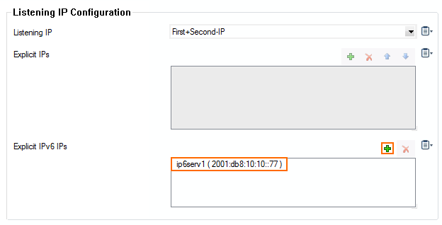
- Click + to add an IPv6 address to the Explicit IPv6 IPs to the list.
- Double click the IPv6 in the list.
- Click Send Changes and Activate.
Step 3. Configuration of the Remote Firewall
Step 3.1. Make the External IP Address Available on the Box Layer
One external IP address must be available on the box layer of the remote firewall to ensure that the management tunnel can be initiated even if the services hosted on the firewall are down. If you are using IPv4 dynamic Internet connection, skip this step.
- Go to CONFIGURATION > Configuration Tree > Multi-Range > your range > your cluster > your managed CloudGen Firewall > Network.
- In the left menu, select IP Configuration.
- Click Lock.
- Click + in the Additional Local IPs section. The IP Address Configuration window opens.
- Configure the additional local IP address:
- Interface – Select the interface for the Internet connection
- IP Address – Enter the external IPv4 address for the managed firewall.
- Responds to Ping – Select Yes.
- Default Gateway – Enter the default gateway supplied by your ISP.
- In the left menu, expand Configuration Mode and click Switch to Advanced View.
- Click + in the Additional IPv6 Addresses section. The Additional IPv6 Addresses window opens.
- Configure the additional local IPv6 address:
- Interface – Select the interface for the Internet connection.
- IP Address – Enter the external IPv6 address for the managed firewall.
- Associated Netmask – Enter the netmask.
- Responds to Ping – Select Yes.
- Click OK.
- In the left menu, click Routing and verify that a default IPv6 route exists. For more information, see How to Configure IPv6 Gateway Routes.
- Click Send Changes and Activate.
Step 3.2. Remote Management Tunnel Settings
- Go to CONFIGURATION > Configuration Tree > Multi-Range > your range > your cluster > your managed CloudGen Firewall > Network.
- In the left menu, select Management Access.
- Click Lock.
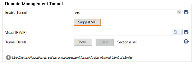
- Set Enable Tunnel to yes.
- To configure the Virtual IP (VIP) for the managed firewall, click on Suggest VIP.
- For the selection of available VIP addresses, there are three options:
- In case no VIP network is defined on your CC, you will be informed that there are no valid VIP addresses available.
- In case there is only one VIP network configured in your CC, the system determines the next available VIP address based on the highest VIP already assigned in the configured VIP network. For example, if the highest VIP address already used is 10.0.80.12, you will be offered the VIP address 10.0.80.13.
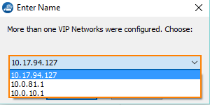
In case there are more than one VIP networks configured on your CC, each of these VIP networks will be checked for the availability of unused VIP addresses. The system will propose the next valid VIP address for each configured VIP network in a list. You must then select which of the proposed VIP addresses will fit your needs.
- Click the Tunnel Details Edit button. The Tunnel Details window opens.
- Enter all IP addresses that need to be reached through the management tunnel to the Remote Networks table. Typically this would be:
- Firewall Control Center IP Address
- Firewall Control Center box layer IP Address
- Authentication Servers IP addresses – E.g, the Active Directory server(s).
- External NTP servers
- Firewall Control Center IP Address
Enter the external IPv4 and IPv6 addresses of the border firewall in the VPN Point of Entry list. You can define multiple points of entry if your border firewall is using multiple ISPs. E.g.,
62.99.0.40- (optional) Use the up and down arrow icons to sort the VPN Point of Entry addresses.
- From the Transport Protocol list, select TCP or UDP. Default: TCP
- From the Encryption Cipher list, select AES-256.
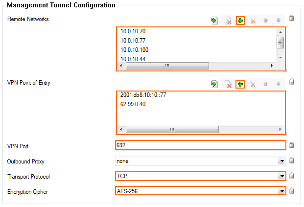
(optional) If needed, you can change the advanced settings for the management tunnel.
- Click OK.
- Click Send Changes and Activate.
Step 4. Create a Dst NAT Access Rule for IPv4 MGMT Tunnels on the Border Firewall
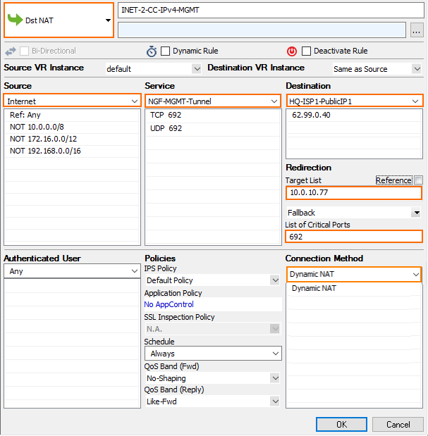
You must create a destination NAT access rule to forward the IPv4 management tunnel traffic to the Control Center:
- Action – Select Dst NAT.
- Source – Select Internet.
- Service – Create and then select a service object to allow TCP traffic on port 692.
- Destination – Enter the IPv4 address configured as a VPN Point of Entry for the management tunnel. E.g.,
62.99.0.40 - Target List – Enter the IP address of the Control Center. E.g.,
10.0.10.77 - List of Critical Ports – Enter 692.
- Connection – Select Dynamic NAT.
Step 5. Create a Pass Access Rule for IPv6 MGMT Tunnels on the Border Firewall
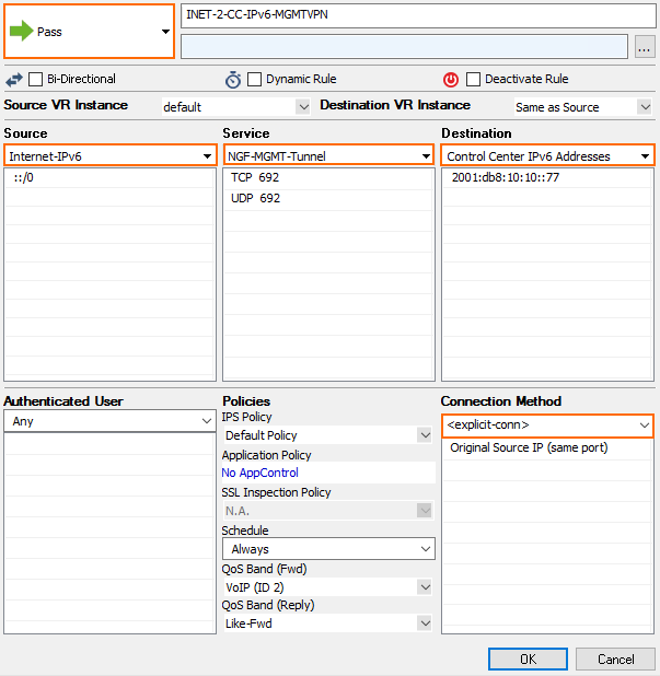
For the remote firewall to reach your Control Center via IPv6, you must allow TCP and UDP 692 connections from the external IP address of the firewall to your Control Center. Create the following IPv6 access rule:
- Action – Select Pass.
- Source – Select Internet or enter the public IPv6 address of the remote firewall.
- Service – Create and then select a service object to allow TCP and UDP traffic on port 692.
- Destination – Enter the IPv6 global unicast address of the Control Center. E.g.,
2001:db8:10:10::77
Step 6. Create and Deploy the PAR File to the Remote Firewall
You must create a PAR file for the remote firewall on the Control Center and then deploy the configuration.
Step 7. (optional) Create Access Rules and Routing Entries for Separate VIP Networks
You only need to complete these steps if you are using VIP addresses that are not part of your local network. You must have a CC firewall service running on the box level of your Control Center. For more information, see Control Center CC Firewall.
Step 7.1 Create a Routing Entry for the VIP Network on the Border Firewall
- Open the Network page for your border firewall (BOX > Network).
- In the left menu, click Routing.
- Click Lock.
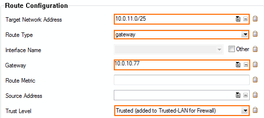
- Add a route for the VIP network:
- Target Network Address – Enter the VIP network. E.g.,
10.0.11.0./24 - Route Type – Select gateway.
- Gateway – Enter the IP address of the Control Center E.g.,
10.0.10.70 - Trust Level – Select Trusted.
- Target Network Address – Enter the VIP network. E.g.,
- Click OK.
- Click Send Changes and Activate.
- Activate the network changes on the Box page (CONTROL > Box).
Step 7.2. Create an Access Rule to on the Border Firewall
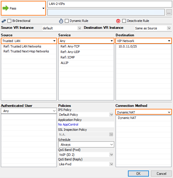
To forward traffic from the local network through the remote management tunnel to the remote firewall, you must create a routing entry on the border firewall and an access rule permitting traffic from the local to the VIP network:
Create the following access rule on your border firewall.
- Action – Select PASS.
- Source – Select Trusted LAN.
- Service – Select Any.
- Destination – Enter the VIP network or select a network object containing the VIP network.
- Connection – Select Dynamic NAT.
Step 7.3. Create an Access Rule in the CC Firewall on the Control Center
You must be running the CC Firewall on the Control Center to create an access rule. For more information, see Control Center CC Firewall.
- Log into the box layer of your Control Center.
- Verify that you are running a CC Firewall service.
- Go to CONFIGURATION > Configuration Tree > Assigned Cervices > Firewall > Forwarding Rules.
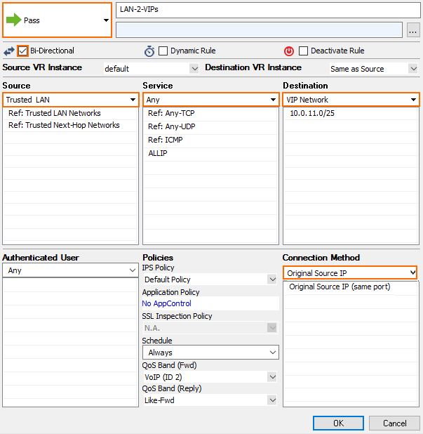
- Create an access rule with the following settings:
- Action – Select PASS.
- Source – Select Trusted Networks.
- Bidirectional – Set the bidirectional checkbox.
- Service – Select Any.
- Destination – Enter the VIP network or select a network object containing the VIP network.
- Connection – Select Original Source IP.
- Click OK.
- Click Send Changes and Activate.
Log in to the box level of your Control Center and go to VPN > Client-to-Site to see the connected remote firewalls.

