For a Barracuda Networks appliance to enforce SD-WAN, TINA tunnels must be established from on-premises appliances to a destination in Azure. This article explains how to create a TINA transport over an Azure ExpressRoute between two Barracuda CloudGen Firewall appliances (one on-premises and one in Azure).
Requirements
- An Azure ExpressRoute.
- A VNET connected to the Azure ExpressRoute with a virtual network gateway.
Before You Begin
- Define the IP addresses that will be used to establish the TINA transport between the on-prem and the cloud device. These IPs must not be used in any local network or advertised network prefix.
The following example uses 192.168.123.1/32 for the cloud CGF appliance and 192.168.123.2/32 for the on-prem CGF appliance.
Azure Barracuda CGF Gateway Deployment
You must deploy a Barracuda CloudGen Firewall appliance in Azure, in a VNET peered to the ExpressRoute.
- Look up the VNET of the Barracuda CloudGen Firewall Gateway.
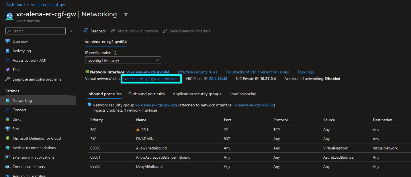
- Peer this VNET to the VNET connected to the ExpressRoute, which has a virtual network gateway:
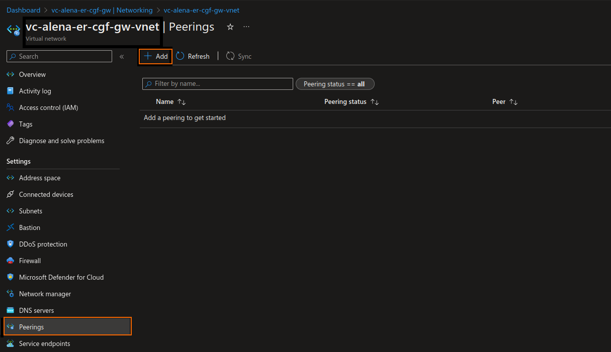
- Under Settings, select Peerings, and click + Add.
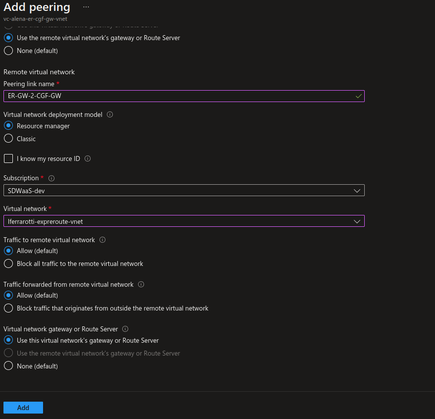
- The Add peering window opens. Under This virtual network, enter a Peering link name that should be used from the initiate network to the ER gateway, e.g.:
CGF-GW-2-ER-GW - Select Use the remote virtual network`s gateway or Route Server.
- Under Remote virtual network, enter a Peering link name for the remote network, e.g.:
ER-GW-2-CGF-GW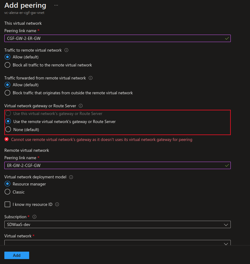
- Under Settings, select Peerings, and click + Add.
- Select the name of your Virtual network, and click Add.
The peering should now be listed with status Connected:
ExpressRoute Setup
Create an Azure private peering:
- Look up the ExpressRoute.
- Go to Settings > Peerings, and select the entry.
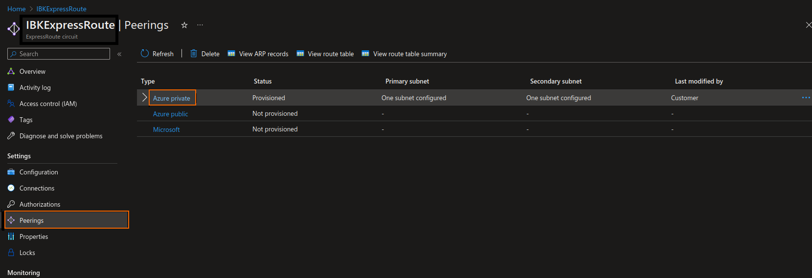
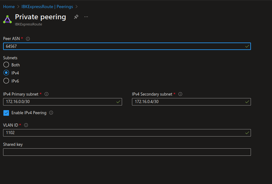
- Define the Peer ASN and the subnet values (the VLAN ID should be given by the ExpressRoute provider)
On-Premises CGF Deployment
Configure the Link to the ExpressRoute Edge Server
The primary and secondary links of the peering must be configured on the on-premises device. In this example, the Ethernet port p5 of the CloudGen Firewall is connected to the ExpressRoute modem. Also, the ER provider gave a VLAN id of 2100 for the primary link and 1100 for the secondary link.
Configure the VLAN Interfaces
- Log into your Barracuda CloudGen Firewall using Firewall Admin.
- Go to Box > Network, and select Virtual LANs in the left menu.
- Configure the VLAN interfaces:
- For the primary link:

- For the secondary link:

- For the primary link:
Configure IP Connectivity
Go to Box > Network > IP Configuration, and configure the links as follows:
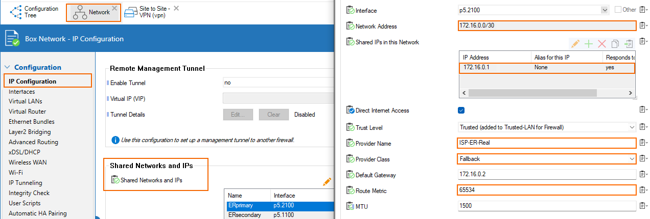
- Primary → the network CIDR is 172.16.0.0/30 in the Azure configuration of the private peering. We are assigned the first IP in this CIDR by MSFT, so 172.16.0.1/30 is configured as a Shared IP on p5.2100 (VLAN interface on p5 with VLAN id 2100)
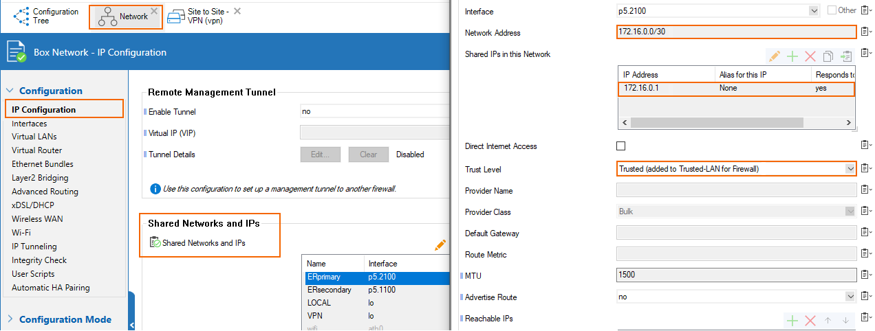
- Secondary → the network CIDR is 172.16.0.4/30 in the Azure configuration of the private peering. We are assigned the first IP in this CIDR by MSFT, so 172.16.0.5/30 is configured as a Shared IP on p5.1100 (VLAN interface on p5 with VLAN id 1100)
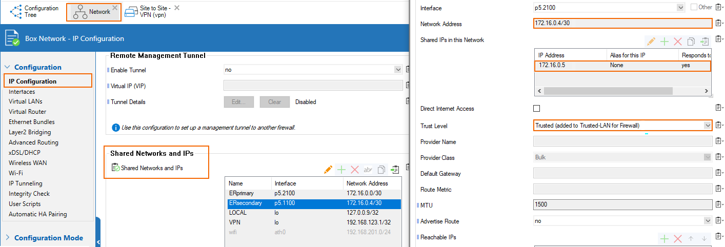
Configuration for HA Deployment Inside Azure
- Primary → the network CIDR is 172.16.0.0/30 in the Azure configuration of the private peering. We are assigned the first IP in this CIDR by MSFT, so 172.16.0.1/30 is configured as a shared IP on p5.2100 (VLAN interface on p5 with VLAN id 2100). Direct Internet Access is enabled for the assigned provider ISP-ER-Real with class Fallback and route metric 65534.
- Secondary → the network CIDR is 172.16.0.4/30 in the Azure configuration of the private peering. We are assigned the first IP in this CIDR by MSFT, so 172.16.0.5/30 is configured as a shared IP on p5.1100 (VLAN interface on p5 with VLAN id 1100). Direct Internet Access is enabled for the assigned provider ISP-ER-Real with class Fallback and route metric 65535.

Configure BGP Peering to the ExpressRoute Gateway
For the BGP configuration of the peering to the ER gateway, we want to achieve 3 goals:
- Establish BGP connectivity
- Advertise the IP (or a CIDR prefix containing the IP) of the VPN endpoint in the cloud and prevent any other prefix to be learned via the BGP peering to the ER GW (using BGP prefix filters)
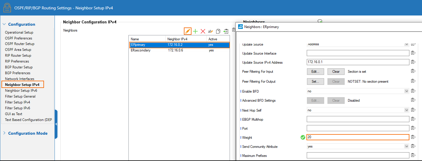
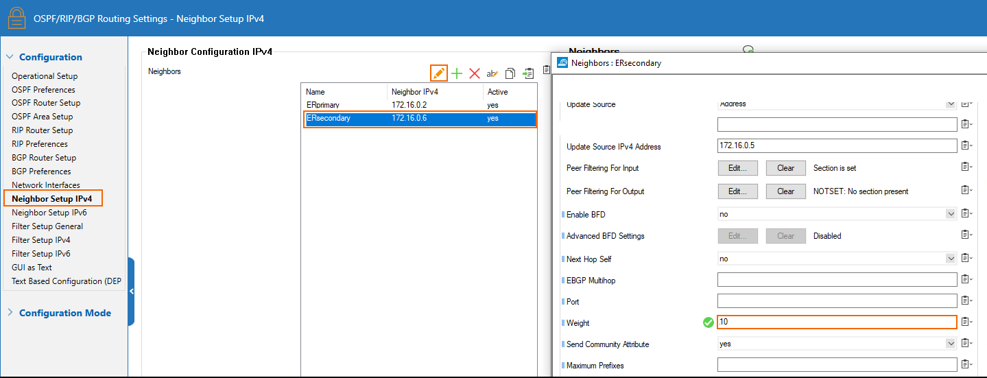
- Prioritize the primary ER link, keeping the secondary as backup, for establishing the TINA transport over the ER (using BGP peer weight)
For general information on how to configure BGP on the CloudGen Firewall, see Dynamic Routing Protocols (OSPF/RIP/BGP).
Establish BGP Connectivity
There is one BGP peer accessible on each of the link of the ER. Create peers for both of them.
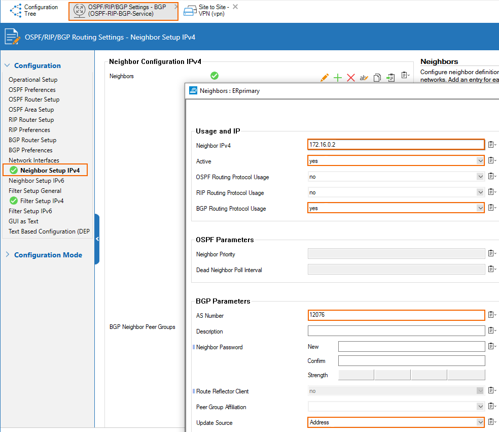
Primary ER Link - BGP Peer Configuration
The IP of the peer is the 2nd addressable IP of the subnet of the ER link. In that case, the subnet of the primary link is 172.16.0.0/30, so the IP of the primary ER BGP peer is 172.16.0.2. ASN of the ER BGP server is 12076 (a public ASN reserved for MSFT).

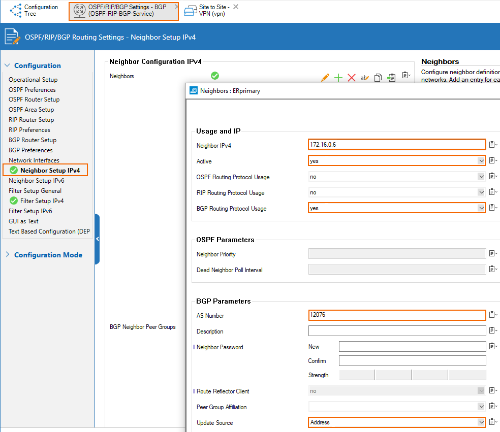
Secondary ER Link - BGP Peer Configuration
The IP of the peer is the 2nd addressable IP of the subnet of the ER link. In that case, the subnet of the secondary link is 172.16.0.4/30 so the IP of the primary ER BGP peer is 172.16.0.6. ASN of the ER BGP server is 12076 (a public ASN reserved for MSFT).

Set Up BGP Prefix Filters
Allow the VNET prefix of the VNET in which the Cloud Barracuda appliance lives (10.27.0.0/16 in our case)
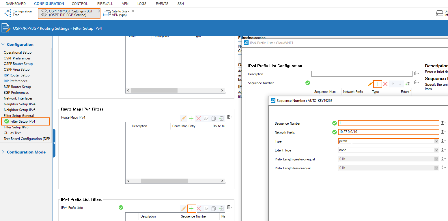
Prevent all other prefixes from being learned.

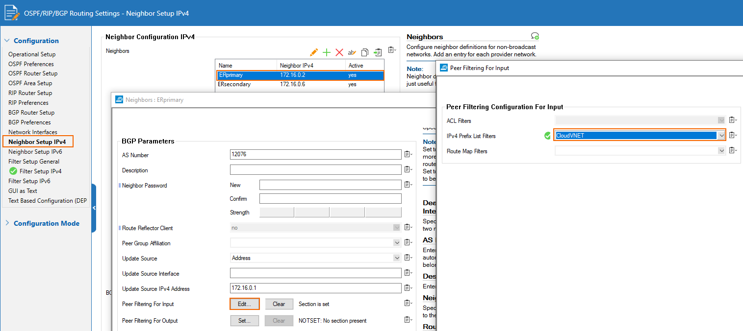
Apply this filter to both peers (for each of the ER links, depicted here only for the primary link → also configure the filter on the secondary link in the same way):
Prioritize the Primary ER Link for TINA Traffic
Configure the ER primary BGP peer with a higher weight than the ER secondary BGP peer:
Check the Configuration
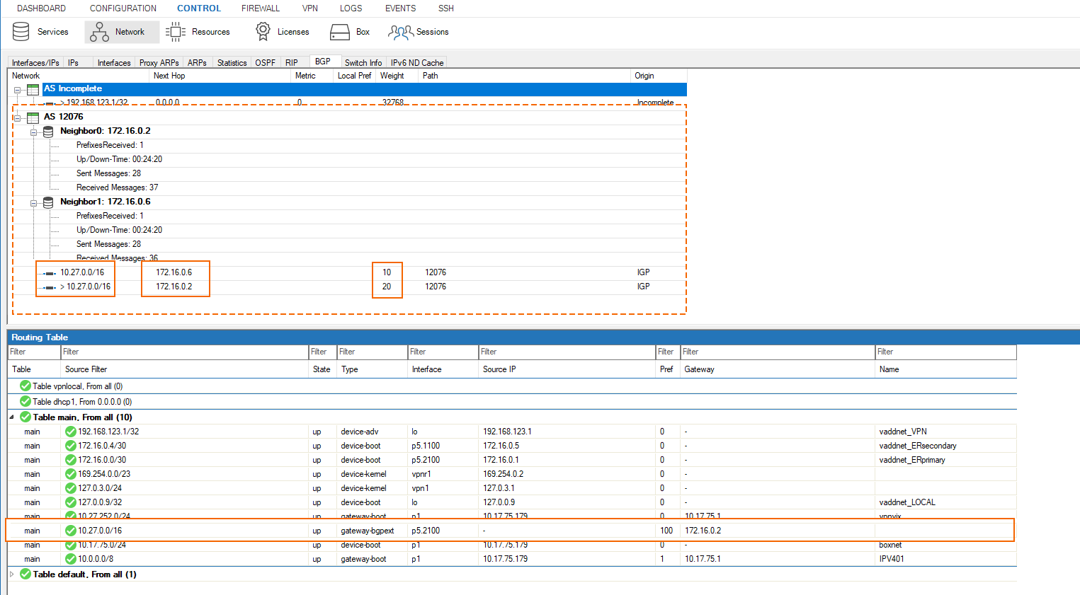
We see only 10.27.0.0/16 coming from both BGP peers. Since the weight of the ER primary BGP peer is higher than the one of the secondary, the route 10.27.0.0/16 is installed with a next-hop of 172.16.0.2, the IP of the ER GW over the primary ER link.
Configure a TINA Transport over the ER
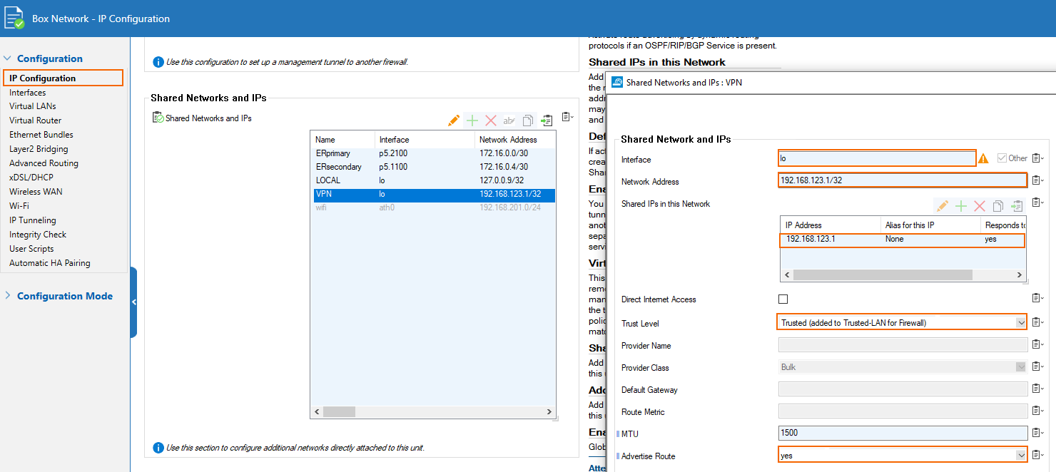
Configure a Virtual Single IP Advertised to the ER GW
Create a service IP introduced on the loopback interface of the on-premises appliance and advertised over the routing service. This IP must not exist anywhere in the whole network of the setup (including in the cloud resources). It will be advertised over the BGP peering to the ER GW to Azure. This is how the Barracuda cloud appliance will know how to route back the TINA traffic for the transport over the ER to the on-premises appliance.
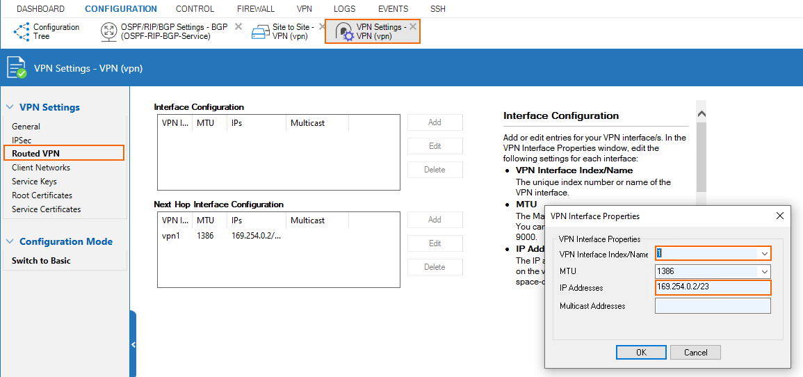
Configure Routed VPN Interface Settings
In this case, we are using the 169.254.0.0/23 subnet for the routed VPN interfaces throughout the setup. The site gets assigned 169.254.0.2.
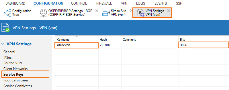
Configure a Service Key
Create a service key in VPN Settings.
Create the TINA Transport
The on-premises device is the active partner of the tunnel on VPN interface of index 1
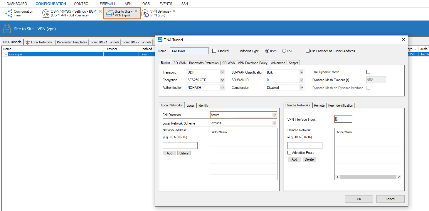
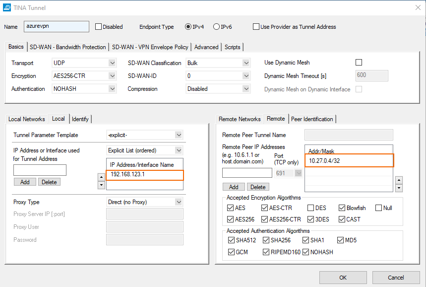
The remote endpoint is the IP of the cloud Barracuda appliance 10.27.0.4. The transport is bound to the virtual single IP introduced on the loopback interface on the on-premises appliance.
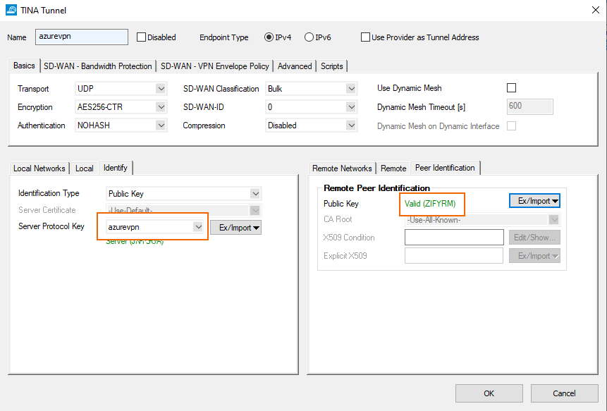
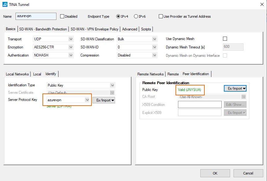
Configure the identification for the tunnel.
Azure Cloud CGF - VPN Configuration
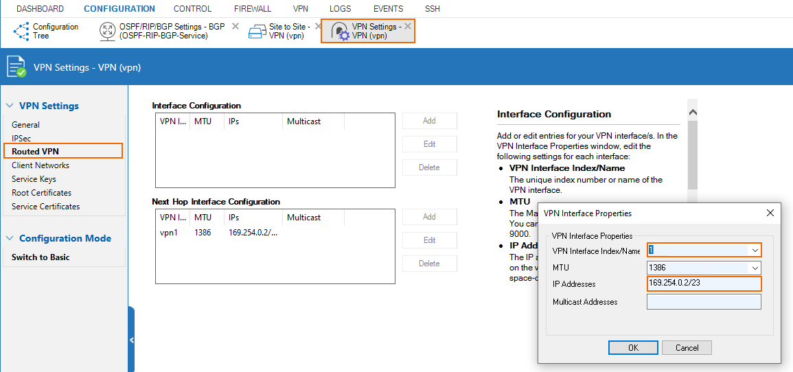
Configure Routed VPN Interface Settings
In this case, we are using the 169.254.0.0/23 subnet for the routed VPN interfaces throughout the setup. The site gets assigned 169.254.0.1.
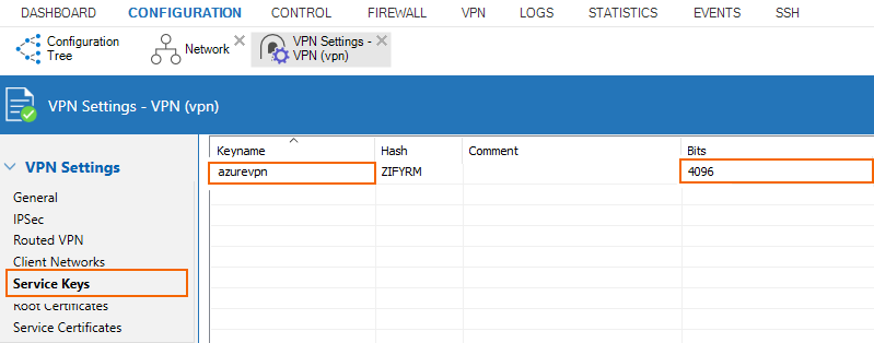
Configure a Service Key
Create a service key in VPN Settings.
Create the TINA Transport
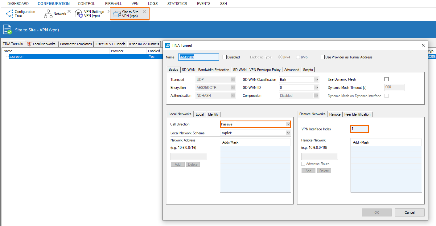
The cloud appliance is the passive partner of the tunnel on VPN interface of index 1.
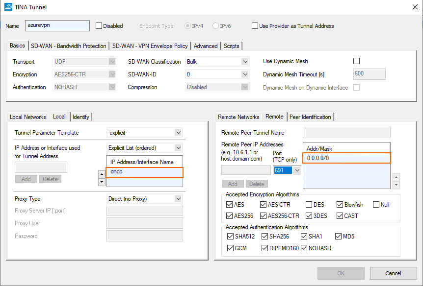
We allow TINA connection from anywhere and bind the transport to the DHCP interface of the cloud appliance.
Configure the identification for the tunnel.
