

This article describes the usage of virtual routers working with ethernet bonds (ethernet bundles) on a VLAN.
The purpose of this article is to exemplify how to build a configuration that facilitates sending traffic over a VLAN which is handled by virtual routers and which is channeled over a bond interface on the CGF. This article also considers a switch that is connected to the CGF via the bond and that forwards the traffic to clients on a LAN.
The article is intended to help understand the underlying concept and to be a supportive example to create a similar setup of any higher complexity.
Before You Begin
- You should be familiar with the concept of virtual routers. For more information on virtual routing and forwarding, see Virtual Routing and Forwarding (VRF).
- The network setup described in this article also refers to a switch that must be connected to the CGF. Ensure that your switch supports the configuration of ethernet bonds with an Active-Backup setup.
Scenario
The Management Interface and LAN1
The CGF is connected to the local network LAN1. The management IP address is configured on the interface eth0. The traffic from LAN1 is forwarded to the WAN by the CGF’s default router.
The Ethernet Bundle and LAN2
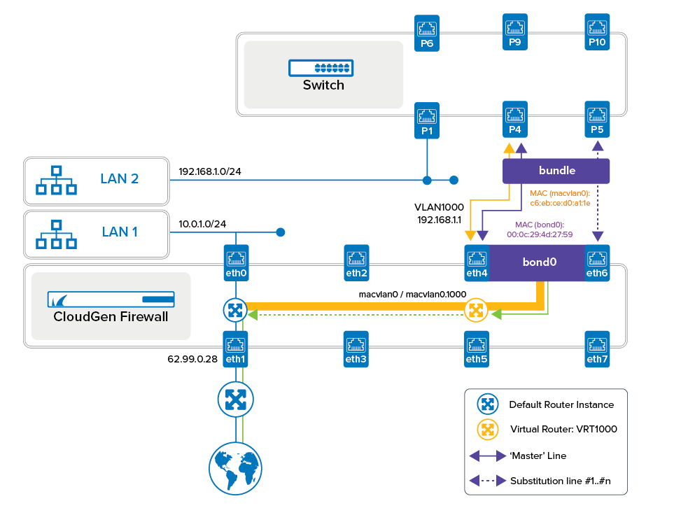
In the image below, port P1 and LAN2 are symbolical placeholders for any given number of clients connected to the switch on the network LAN2.
The bond on the CGF uses interface ports eth4 and eth6 and is connected to ports P4 and P5 on the switch. To work correctly, the switch is configured in the same way as the CGF, and both appliances run an ethernet bond as an Active-Backup setup.
In such a setup, a new virtual interface is created, and during the configuration, you must assign an identifier to this virtual interface by selecting from a list of 16 entries, ranging from bond0 to bond15. The bundle consists of multiple wired ethernet connections (i.e., eth4 and eth6) which are handled by a special driver that controls the flow of information over those lines.
In the active-backup setup, the first configured line that actively transmits information (i.e., eth4) is in all technical operating system manuals referenced as the 'master' line. If this line fails, the underlying driver immediately switches to the next configured line to substitute the previous one until its connection becomes reestablished. This failure-switching continues until the last configured line in the bundle becomes activated. The switching process in the reverse direction keeps going until the 'master' line becomes active again.
On the level of MAC addresses, the corresponding driver replaces the different generic MAC addresses of all bundled interfaces with a common, identical MAC address. To technically address and access the bundle, it inherits the MAC address from the first configured ethernet MAC interface in the bundle.
The following table shows the configuration of the MAC addresses for multiple connection lines as part of a common bundle interface (bond0) in an active-backup setup.
| Interface | Usage | MAC Address | Note |
|---|---|---|---|
| eth0 | Standard | 00:0c:29:4d:27:6d | MIP on LAN1 |
| eth1 | Standard | 00:0c:29:4d:27:95 | WAN |
| .... | |||
| eth4 | bond0 | 00:0c:29:4d:27:59 | Master line of bond0 |
| eth6 | bond0 | 00:0c:29:4d:27:59 | Substitution line (#1) for eth4 |
| .... | bond0 | 00:0c:29:4d:27:59 | Optional: substitution line (#2) for eth6 |
| ethX | Standard | 00:0c:29:4d:27:xx |
As a consequence, the connected switch doesn't need to learn a new MAC address during a failover, thus ensuring that traffic is always forwarded transparently between the CGF and the switch and providing a minimal switch-over time and optimal continued throughput.
Using VLANs on Bond in Virtual Routers
In addition to the requirements above, the traffic from LAN2 over the bond must be transmitted over a VLAN. To achieve this, the CGF provides the MACVLAN option in the Advanced View mode of Firewall Admin that facilitates using VLANs to be used in virtual routers on top of a bond interface. When such a MACVLAN interface is created, a new MAC address will be configured for it to work as a wrapper for the underlying bond interface. The MAC address of the underlying bond interface can from then on no longer be accessed directly.
After creating the required virtual router, a shared IP address can be configured and assigned to the new MACVLAN interface. Due to the MACVLAN option, the VLAN can now be handled by virtual routers, and traffic can also be forwarded between the default router and any additional configured virtual router.
In this example, the virtual router VRT1000 hands over traffic from LAN2 to the default router which in turn forwards the traffic to the WAN.
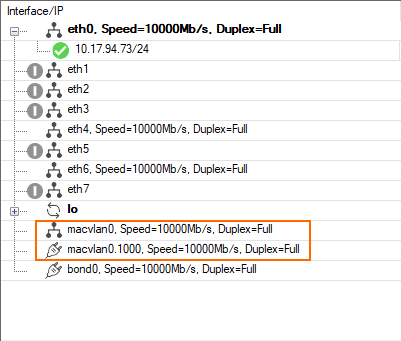
The thick orange line in the figure above indicates that VLAN1000 is configured on the macvlan0 interface with the IP address 192.168.1.1, and that the macvlan0 and macvlan0.1000 interfaces on top of the bond0 interface can be handled by any configured virtual router, i.e., VRT1000.
The thin orange line indicates that traffic through the VLAN1000 interface is transmitted on top of the active line (i.e., eth4) of the bond0 interface. In case of a failover, this line will be switched to the next configured bond interface (i.e., eth6).
Allowing Traffic to Be Forwarded Between Multiple Router Instances
Finally, to enable traffic flow between the default and any additional virtual router, an appropriate access rule must be created.
How to Configure the CGF to Operate VLANs on an Ethernet Bond with Virtual Routers (VRFs)
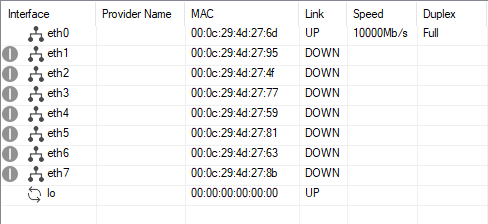
The configuration of the CGF for the described scenario will cause multiple changes that can be tracked optimally in the table at CONTROL > Network, tab Interface.
Initially, the interface table looks like this:
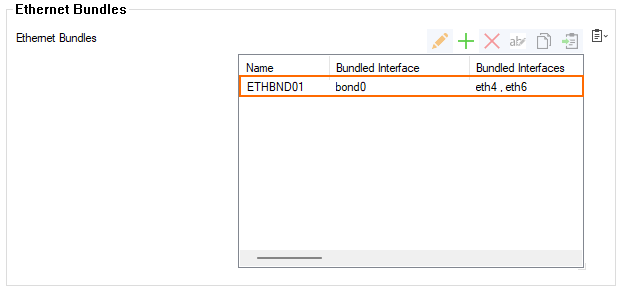
Step 1. Create the Ethernet Bundle 'bond0'
The ethernet bundle must be created from eth4 and eth6 and will be named bond0.
- Log into your firewall.
- Go to CONFIGURATION > Configuration Tree > Box > Network > Ethernet Bundles.
- Click Lock.
- Click the green '+' on top of the Ethernet Bundles Configuration table.
- The Ethernet Bundles dialog window is displayed.
- Enter the name of the bundle. E.g.,
ETHBNDL01 - The Ethernet Bundles : ETHBND01 window is displayed.
- The field Bundled Interface is initially preset with the identifier
bond0unless another bundle is already present. - Click the green '+' to add the first bundle interface
eth4. - Double-click
eth4in the menu list. - The interface is added to the table.
- Double-click
eth6in the menu list. - The interface is added to the table.
- Click OK.
- Click Send Changes.
- The window Boxnet Activation required is displayed.
- Click OK.
- Click Activate.
- The Activate Changes window is displayed.
- Click Activate.
- Go to CONTROL > Box.
- Expand the Network entry in the left menu area.
- Click Activate new network configuration.
- The Network Activation window is displayed.
- Click the Activate now button.
Step 1a. Configure the Same Bond on Your Switch
Configure your switch to use 2 ports as an ethernet bond to operate in Active-Backup mode and connect the CGF to the switch with 2 ethernet cables. Ensure that the corresponding ports (master and substitution) are connected suitably.
Step 2. Check that the Bundle Interface has been Created
- Go to CONTROL > Network.
- The newly created bundle interface
bond0is displayed in the list. - Note that the MAC address of the first configured interface
eth4has been assigned to the bundlebond0and to all contained additional interfaces, i.e.eth6.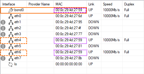
The driver for handling the ethernet bundle now manages all contained interfaces transparently. Ifeth4fails, traffic will immediately be transmitted througheth6. - Go to CONFIGURATION > Network > Interfaces.
- Note that in the section Physical Interfaces, the interfaces
eth4andeth6now report their availability status as RESERVED.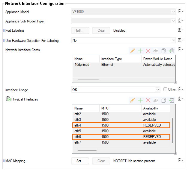
- Go to CONFIGURATION > Network > Virtual Router.
- Note that the bundle interface
bond0has been added at the beginning of the table for VR InstanceInterface Assignment.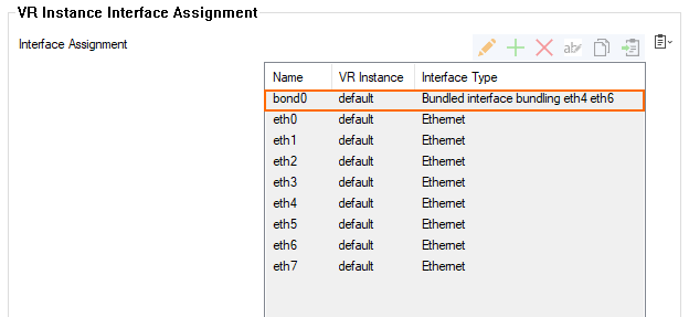
- It is now possible to also create VLANs on top of the bundle if required. However, note at this stage that VLAN traffic on a bundle can only be transmitted through the default router.
Step 3. Enable Transferring Traffic through Virtual Routers
Because only the default router can forward traffic through VLANs on top of a bundle interface, it is necessary to introduce a new virtual interface on top of the bundle which then facilitates also virtual routers to handle VLAN traffic on a bond.
To enable virtual routers to do so, perform the following steps:
- Go to CONFIGURATION > Network > Ethernet Bundles.
- Ensure that you have selected Advanced Configuration mode in the left menu area.
- Click Lock.
- Double-click the entry of your ethernet bundle.
- The Ethernet Bundles : ETHBND01 window is displayed.
- For Use a MACVLAN interface with Bundle, select Yes.
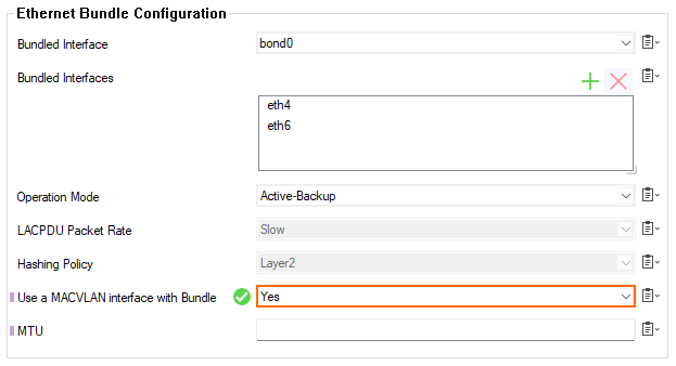
- Click OK.
- Click Send Changes.
- The window Boxnet Activation required is displayed.
- Click OK.
- Click Activate.
- The Activate Changes window is displayed.
- Go to CONTROL > Box.
- Expand the Network entry in the left menu area.
- Click Activate new network configuration.
- The Network Activation window is displayed.
- Click the Activate now button.
Step 4. Check that the MACVLAN Interface has been Created
Creating a virtual MACVLAN interface on top of the bundle interface facilitates virtual routers to handle traffic between source and destination interfaces and also allows forwarding traffic between different virtual routers and/or the default router on the CGF. Thus, traffic can be received from a source by a virtual router and can be sent to the destination by another virtual or by the default router.
To check the new virtual interface in the interface table, perform the following steps:
- Go to CONTROL > Network.
- The newly created virtual interface
macvlan0is displayed in the list. Note that the
macvlan0interface now uses a different virtual MAC address like the underlyingbond0interface!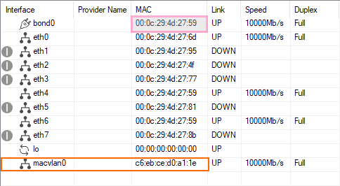
The underlying driver still handles failovers on the bond, however, thebond0MAC address (i.e.,00:0c:29:4d:27:59) is now overridden by the newmacvlan0MAC address (i.e.,c6:eb:ce:d0:a1:1e).- Go to CONFIGURATION > Network > Virtual Router.
- Note that the bundle interface
macvlan0has been added at the beginning of the table for VR InstanceInterface Assignment.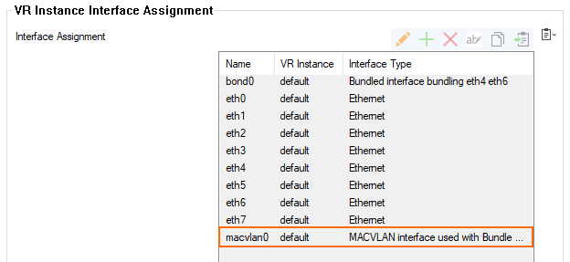
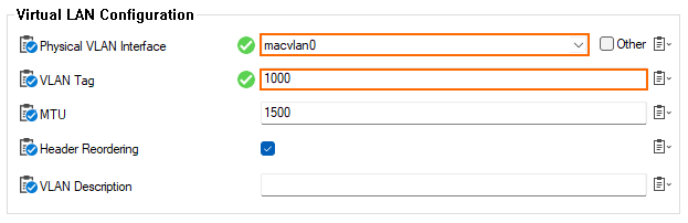
Step 5. Create a VLAN on top of MACVLAN0
After creating the MACVLAN virtual interface that can be handled by virtual routers, you can now configure your individual VLAN with the ID 1000 on top of the macvlan0 interface.
- Go to CONFIGURATION > Network > Virtual LANs.
- Click Lock.
- Click the green '+' on top of the Virtual LANs table.
- The VLANs window is displayed.
- Enter the name for the VLAN, i.e. VLAN1000.
- Click OK... .
- The VLANS : VLAN1000 window is displayed.
- For Physical VLAN Interface, select
macvlan0from the list. - For VLAN Tag, enter 1000.
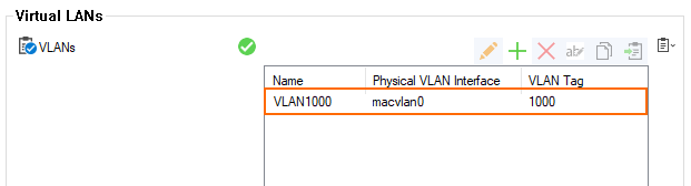
- Click OK.
- The table in the Virtual LANs section now contains the new VLAN1000 entry.
- Click Send Changes.
- Click Activate.
- The Soft Boxnet Activation sufficient window is displayed.
- Click OK.
- Click Activate.
- The Activate Changes window is displayed.
- Click Activate.
- Go to CONTROL > Box.
- Expand the Network entry in the left menu area.
- Click Activate new network configuration.
- The Network Activation window is displayed.
- Click the Activate now button.
- The Network Activation window is displayed.
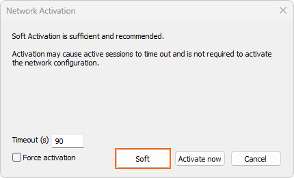
- Click the Soft button.
Step 6. Check the Configuration of the New MACVLAN0 Interface
- Go to CONFIGURATION > Network > Virtual Router.
- Note that the bundle interface
macvlan0has been added at the beginning of the table for VR InstanceInterface Assignment.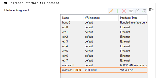
- Go to CONTROL > Network.
- The newly created virtual interface
macvlan0is displayed in the list. Note that the
macvlan0.1000interface now uses the same virtual MAC address as thebond0interface, but the same virtual MAC address as themacvlan0interface.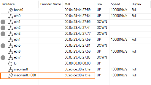
- Go to CONTROL > Network, tab Interfaces/IPs.
- Note that the VLAN interfaces are now listed, but they have no IP address assigned yet!
How to Configure a Virtual Router to Use the Newly Created MACVLAN0.1000
Before routing traffic from LAN2 to the WAN, you must first create a virtual router.
Step 1. Create the Virtual Router VRT1000
To hand over traffic between virtual routers and the default router, the virtual router must be associated with the VLAN1000. To achieve this, perform the following steps:
- Go to CONFIGURATION > Configuration Tree > Network.
- Right-click the Network node in the configuration tree.
- A menu list is displayed.
- Select Create VR Instance from the menu list.
- The Create a new VR Instance dialog window is displayed.
- Enter the name of your new virtual router instance, i.e.,
VRT1000. - Click OK.
- The node for the new virtual router is added as a child node to the Network node. This is because the default router is directly related to the Network node and can not be deleted. In contrast, a virtual router node can be removed at any time if no longer needed.
- Click the '+' symbol to expand the Network node.
Step 2. Assign the New Virtual Router to the VLAN
- Go to CONFIGURATION > Configuration Tree > Network > Virtual Router.
- Click Lock.
- Double-click the
macvlan0.1000entry. - The Interface Assignment : macvlan0.1000 window is displayed.
- For VR Instance, select
VRT1000from the menu list.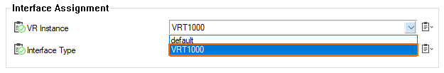
- Click OK.
- Click Send Changes.
- The No Boxnet Activation required window is displayed.
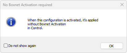
- The virtual router is now assigned to the
macvlan0.1000interface.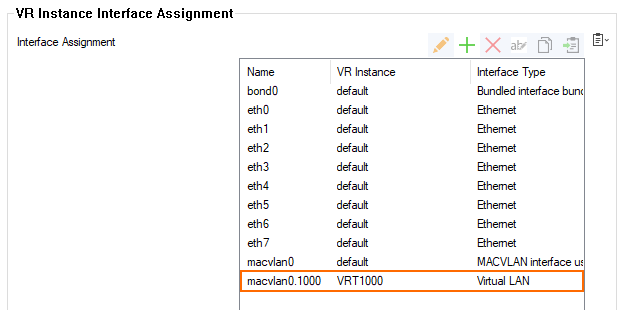
- Click Activate.
Step 3. Assign the VLAN1000 with a Shared IP to the Virtual Router
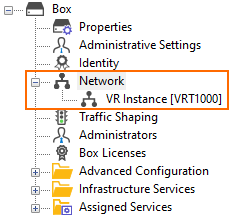
- Go to CONFIGURATION > Network > VR Instance [VRT1000].
- Click IP Configuration in the left menu column.
- Click Lock.
- Click the green '+' on top of the Shared Networks and IPs table.
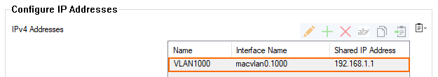
- The IPv4 Addresses window is displayed.
- Enter the name to identify the shared IP address, i.e.
VLAN1000. - The IPv4 Address Configuration window is displayed.
- If the previous VLAN configuration is the only one, the value for Interface Name is already preset to
macvlan0.1000. Otherwise, selectmacvlan.01000from the list. - Enter
192.168.1.1for Shared IP Address. - Select yes for Responds to Ping.

- Click OK.
- Click Send Changes.
- Click Activate.
Step 4. Check that the Firewall Updated the New Configuration
After activating the configuration for the VLAN, you can check how the interface has been moved to the assigned virtual router.
- Go to CONTROL > Network.
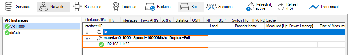
- In the left menu column, locate the entry for the configured virtual router and click VRT1000.
- In the left menu column, click default to display the interface setting for the default router.
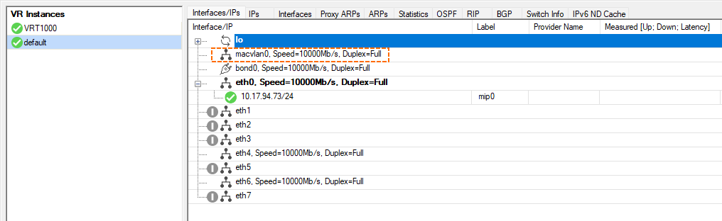
As the screenshots show, the macvlan0.1000 interface has been assigned to the virtual router VRT1000 with the Shared IP 192.168.1.1 assigned to it. In comparison, the macvlan0 interface has not been used and is therefore still located in the scope of the default router.
How to Forward Traffic from LAN2 between Virtual Routers to the WAN
To forward traffic from LAN2 over the virtual router VRT1000 to the default router and the WAN, an appropriate access rule must be created to hand traffic over from the virtual router to the default router. For this, perform the following steps:
- Go to CONFIGURATION > Configuration Tree > Assigned Services > NGFW (Firewall) > Forwarding Rules.
- Click Lock.
- Click '+' to add an access rule.
- For the access rule type, select Pass.
- Enter the name for the new access rule, i.e., LAN2-via-VRT1000-to-WAN.
- Set the following values for the listed parameters:
- Source VR Instance –
VRT1000. - Destination VR Instance –
default. - Source – Enter the IP address of the source network, i.e.
192.168.1.0/24 - Service –
Any. - Destination – Enter the IP address for the Internet from the list.
- Policies – Set the value according to your preferences for using policies or not.
- Connection Method –
Dynamic NAT. 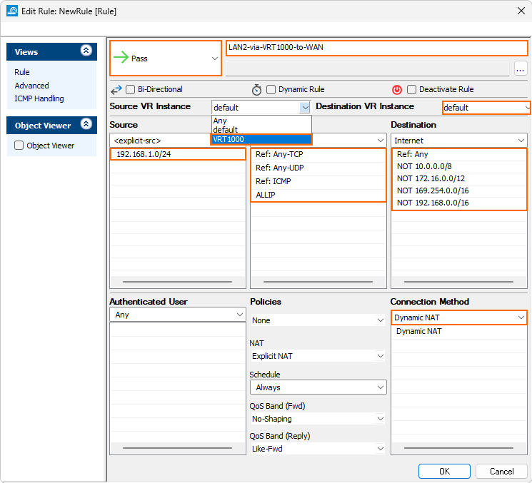
- Source VR Instance –
- Click OK.
- Click Send Changes.
- Click Activate.
The CloudGen Firewall can now forward traffic from the LAN2 network via the virtual router VRT1000 and the default router to the WAN.