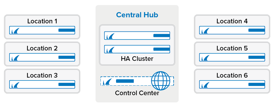
The Barracuda CloudGen Firewall and Firewall Control Center are both designed for the quick deployment and easy management of a large number of CloudGen Firewalls. The Control Center offers features that allow you to apply the parts of the configuration that are the same or similar on all the CloudGen Firewall units. In this example, we are configuring a VPN hub with remote firewalls connected via Site-to-Site VPN. By employing repositories, global/range/cluster Firewall Objects, and shared services, the configuration path is designed to be as efficient as possible. Employing Firewall Objects enables you to quickly change or add additional networks without having to change the configuration of your VPN network.
Section 1 - Preparation
Before You Begin
- The Firewall Control Center must use the same or later firmware version as the managed unit.
- For future reference, create a table with the following information for each CloudGen Firewall:
- A list of local VPN networks to route through the tunnels.
- All public IP addresses to be used for the VPN service.
Preparing the Firewall Control Center
Organizing Your Firewalls into Clusters and Ranges
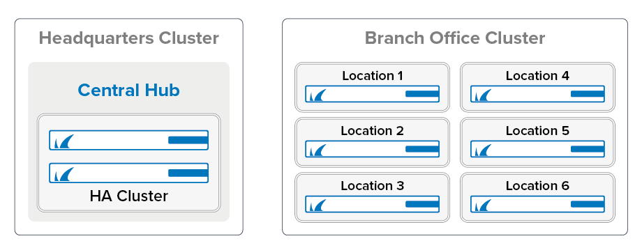
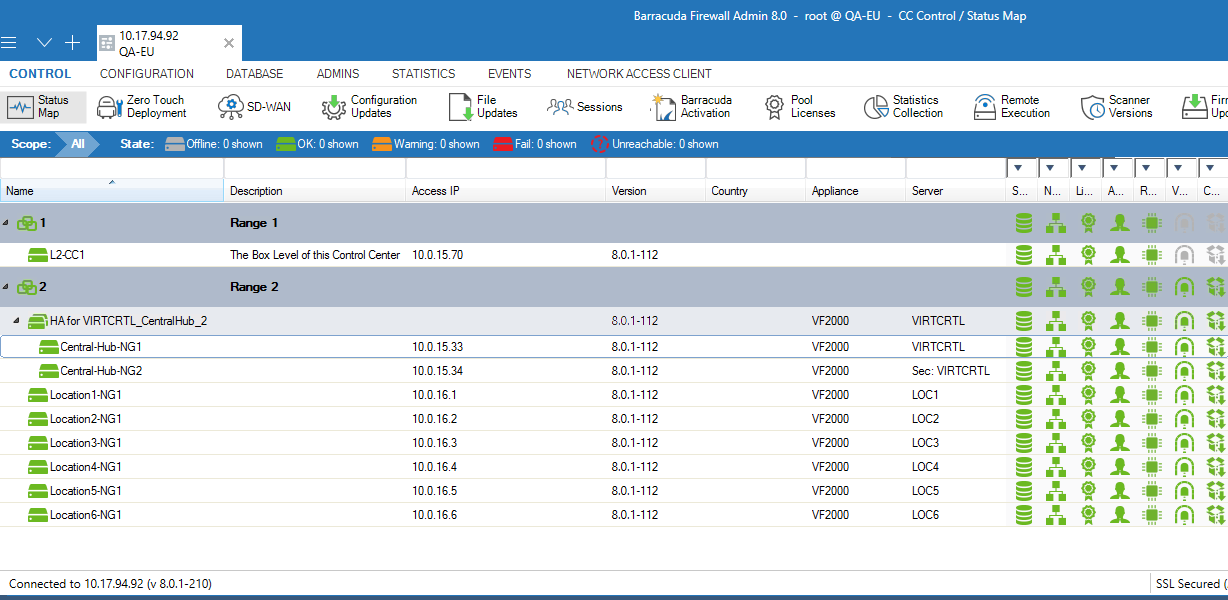
To be able to use distributed services and global firewall objects efficiently, you must organize your firewalls in the respective clusters and ranges. If all your firewalls are running the same firmware version, you can use just one cluster. If some of your firewalls are running an older firmware version, you will need to create a cluster for each version. In this example, the headquarters and branch office firewalls will each use their own cluster since using multiple clusters makes managing the configuration easier.
Branch Office Clusters – Add all branch office CloudGen Firewall units to this cluster. All units must use the same firmware version. These CloudGen Firewall units will share a Distributed Firewall service.
- Headquarters Cluster – The central firewall, which is used as the VPN hub, shares a smaller part of the configuration of the branch office firewall units and does not use the distributed services.
For more information, see How to Manage Ranges and Clusters.
Global Firewall Objects
Global Firewall Objects allow you to enter the network addresses once for all the networks, public IP addresses, and special servers, and then to reuse them when configuring the services. A Global Firewall Object on the global or range level can be overridden by a different IP address or network on the range or cluster level. This allows for one-time configurations in cases where one cluster uses a different IP address or network from all other configurations. You can also employ this functionality to enforce the usage of the same firewall object names for all your configurations. This allows you to create repository entries to be reused for all clusters. Site-specific firewall objects are globally defined in name and type, and the IP addresses or networks are entered in CONFIGURATION > Configuration Tree > Network > IP Configuration. Site-specific Network Objects can be used only in the Forwarding and Distributed Firewall services.
Create site-specific network objects for networks or server IP addresses (for example, your exchange servers that differ for each location). Avoid using the generic network object type; instead, be as specific as possible. For this example, create the following global network objects for each location:
- Single IP Address Network Object – Create a network object for each public IP address used by the CloudGen Firewall. Also, create an empty network object for the VPN next hop interface IP address, which will be filled in later.
- Single Network Addresses – Create a network object for each network routed through the tunnel.
- List of Network Addresses – When using multiple networks in the same location, it is useful to have a network object that references all the networks in that location. This network object is updated automatically whenever one of the network objects it references is updated.
For more information, see Global Firewall Objects.
(optional) Firewall Objects Naming Conventions
Although not required, following a naming convention for the global firewall objects simplifies configuration. It also lets you know at first glance what data is stored in the global firewall object. Also, setting the Network Color makes a network object easily identifiable in the GUI. For this example, we are using the following:
<Location><location number>_<Type(NET, VIP, ... )>_<modifier. E.g., ALL, numbering, etc...>
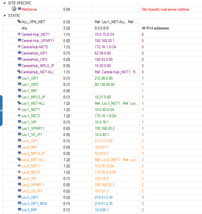
Create Global Firewall Objects
Firewall Object Name | Type | Include Entries |
|---|---|---|
RemoteMGMTIPs | List of IP Addresses | Include all IP addresses that must be accessed through the remote management tunnel. |
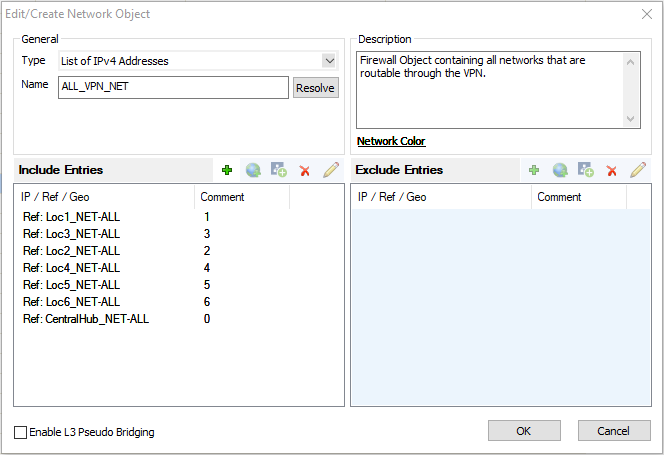
ALL_NET | List of Network Addresses | Contains all networks that are allowed to send and receive traffic through the VPN tunnels. Only add the locX_NET_ALL network object for each location to this network object. |
MailServer | Site-Specific Network Object | In this example, the mail server IP address must be configured for each location. |
Create a Repository
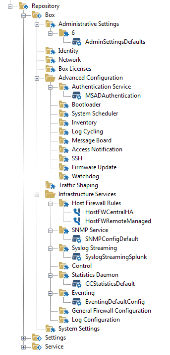
The repository stores preconfigured configuration nodes that can be linked or copied to an individual CloudGen Firewall. You can store several versions of the same configuration node.
- Creating new Firewalls – Link repository entries to the Default Box of the cluster. All the links will be used when new boxes are created in the cluster. You do not have to set up new firewalls in that cluster from scratch.
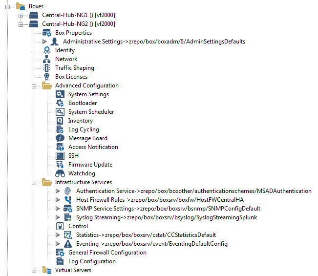
- Existing Firewalls – Prepare the configuration of a service in the repository. Depending on the amount of customization necessary, link or copy the repository entry. Settings for linked repository entries can be overridden.
The nodes stored and used in the repository depend on the network and personal preference of the admin. The following nodes are frequently used:
- Administrative Settings
- Authentication Service
- Host Firewall Rules
- SNMP Service Settings
- Syslog Streaming
- Statistics
- Eventing
For more information, see Repositories.
Preparing the Managed Firewalls
The CloudGen Firewall units must be managed by the Control Center and have connection to the Internet.
For more information, see Central Management and WAN Connections.
Create Services
You must create the necessary services:
- Forwarding Firewall / Distributed Firewall Service – Reduce the overhead of maintaining a large number of very similar rulesets by using a Distributed Firewall for all firewalls in a cluster.
- VPN Service
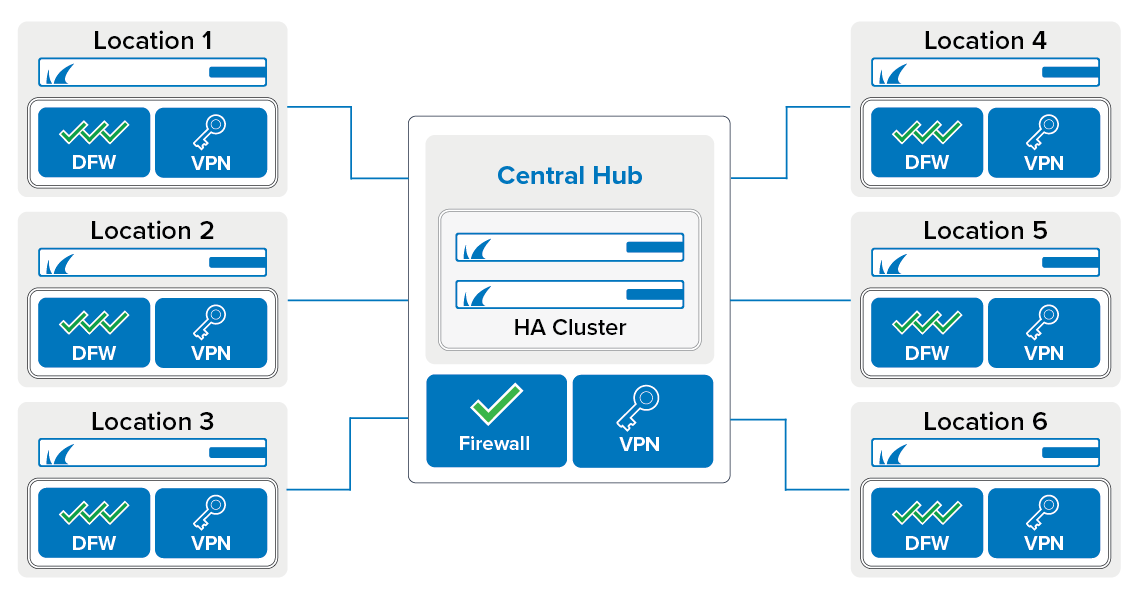
Section 2 - Setup Overview
Site-to-Site VPN Tunnel Network
TINA VPN Tunnels
Site-to-Site VPN tunnels on the CloudGen Firewall use the Barracuda-proprietary VPN protocol. TINA offers many enhancements not featured in the standard IPsec protocol, such as SD-WAN, Traffic Compression, and WAN Optimization. SD-WAN allows you to prioritize data flow and distribute VPN traffic between multiple Internet connections. WAN Optimization and Compression reduces the amount of traffic sent through the tunnel by using data deduplication.
Depending on the type of traffic you are sending through the VPN tunnel, choose one of the following VPN transport modes:
- UDP – UDP encapsulation benefits from the low-overhead, reduced latency (Round Trip Time), and NAT traversal capabilities of the UDP protocol. UDP has no error checking, which may be a problem for connections with high packet loss or if VPN traffic largely consists of UDP connections.
- TCP – TCP offers transport reliability and NAT traversal capabilities. It is the only available option if you are behind a proxy. If you must connect through an HTTP proxy, port 443 can also be used.
- Hybrid (TCP & UDP) – A Hybrid mode tunnel encapsulates TCP in UDP and UDP in TCP to balance the strengths of each protocol with optimal transport reliability. Latency-critical UDP traffic should not be sent in Hybrid mode because the TCP transport mode may increase the latency.
- ESP – ESP is the native IPsec protocol, and as a layer 3 protocol, it offers the best performance. NAT traversal is not possible.
- Routing – No encapsulation is performed for this transport mode.
Firewall or Distributed Firewall
The Distributed Firewall is designed to lower the overhead of maintaining a large number of firewalls where each firewall services contains the same access rules. To change an access rule for every remote location, you only have to change one access rule in the Global Ruleset of the Distributed Firewall. Unique access rules can still be created in the special or local ruleset that are specific to each location. Since the central location does not share the same access rules, using a forwarding firewall service instead of the distributed firewall service is the better choice.
Section 3 - Configuration Tasks for Every CloudGen Firewall
The following tasks must be completed for each unit:
- Create network objects for network and public IP addresses. For example, HQ_LAN, HQ_DMZ, HQ_ALL_NET
- Configure VPN GTI Settings.
- Configure the GTI Networks and enter the IP addresses and networks for the site-specific network objects you created in the global firewall objects.
Create Global Firewall Objects
| Firewall Object Name | Type | Include Entries |
|---|---|---|
| LocX_ISP1 | Single IP Address | Public IP address for the first ISP |
| LocX_ISP2 | Single IP Address | Public IP address for the second ISP |
| LocX_MPLS_IP | Single IP Address | IP address for the MPLS connection |
| LocX_VIP | Single IP Address | VIP IP address |
| LocX_VS_IP1 | Single IP Address | Shared IP – Internal IP address of the firewall services. |
| LocX_NET1 | Single Network Address | First network in location X |
| LocX_NET2 | Single Network Address | Second network in location X |
| LocX_NET3 | Single Network Address | Third network in location X |
| LocX_NET_ALL | List of Network Addresses | LocX_NET1, LocX_NET2, LocX_NET3 - all networks used in location X |
Add List of Local Network to Global Firewall Object
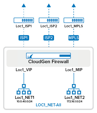
Add the Loc<Location Number>_NET_ALL network object to the ALL_NETS network object. We will use this network object later for the access rules.
For example, for Location 1:
VPN Service Properties
Configure the IP address the VPN service listens on. If you are using firewalls with a dynamic Internet connection (DHCP, xDSL,..), use 127.0.0.1 as the Service IP and create an App Redirect access rule to redirect VPN traffic to the VPN service.
For more information, see How to Configure VPN Access via a Dynamic WAN IP Address.
VPN GTI Settings
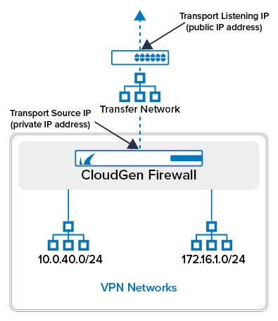
The GTI Editor uses the public IP addresses in the VPN GTI Settings and the VPN Group information to create the VPN tunnels. If you want to use all the service IP addresses you set in the VPN Service Properties, you can use the default values. You can also explicitly enter the IP address the remote CloudGen Firewall connects to (Transport Listening IP) and the Service IP address (Transport Source IP) in the GTI Editor Settings. These two IP addresses will be the same if your CloudGen Firewall connects directly to the Internet. Setting the IP addresses explicitly is useful when configuring more than two public IP addresses or when safeguarding against breaking your VPN configuration in case the first or second IP address of the service is changed. If you are using only active VPN connections from this VPN service, you can disable the Transport Listening IP by entering 127.0.0.1 as the Explicit Transport Listening IP.
Transport Settings for Firewalls with Static Internet Connections:
- Transport Source IP – Select <All-Service-IPs>.
- Transport Listening IP – Select <Use-Transport-Source-IP>.
Transport Settings for Firewalls with a Dynamic Internet Connection:
- Transport Source IP – Dynamic(via-routing). The CloudGen Firewall uses a routing table lookup to determine the source IP.
- Transport Listening IP – Select Explicit to not accept incoming VPN connections on dynamic Internet connections. Otherwise, select <Use-Transport-Source-IP> if you want to use DynDNS hostnames for incoming VPN connections.
- Explicit Transport Listening IP – Enter
127.0.0.1if you are not going to handle incoming VPN connections.
For more information, see How to Configure VPN GTI Settings for a VPN Service.
Add Networks to the Assigned Services
The networks used as local networks by the GTI Editor are configured in CONFIGURATION > Configuration Tree > Network > IP Configuration of each CloudGen Firewall. Use the LocX_NET_ALL network object. Referencing network objects instead of directly entering the networks has the advantage that adding a network to a location is as simple as editing the corresponding network object.
For more information, see Assigned Services.
Section 4 - VPN GTI Editor
For a network with a large number of Site-to-Site VPN tunnels, it is not practical to configure each tunnel separately on both endpoints. The GTI Editor on the Control Center simplifies and automates this task. Add the VPN services managed on the Control Center into a VPN group. Each VPN group shares VPN configuration settings for encryption, Transport (TCP/UDP/TCP&UDP), and basic SD-WAN configuration.
Create VPN Group
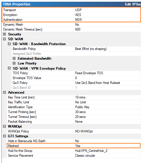
Create the VPN group for this example. Depending on your setup you may need more than one VPN Group to accurately depict your network. Note that using multiple VPN groups will remove the ability to automatically create a fully meshed network. Create the group using the following settings:
- Transport, Encryption, and Authentication – Accept the default, or change to match your internal encryption guidelines.
- Packet Balancing – Select only Cycle within a Transport Class if all of your transports have the same bandwidth and packet round-trip times. If this is not the case, configure session-based balancing in the Connection Object of the access rule that is handling VPN traffic.
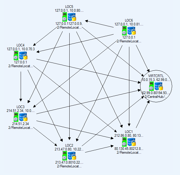
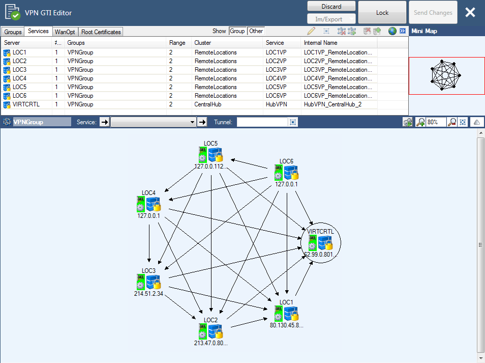
- Meshed – When set to yes, the GTI Editor will automatically create a fully meshed VPN network where all firewalls are connected to each other. Depending on the number of Firewalls involved, this may not be desired because too many site-to-site tunnels can overload the smaller CloudGen Firewall models. In this case, you will have to create the tunnel via drag and drop. For our example, select yes since we want the GTI Editor to create the tunnels.
- Service Placement – Classic circular. This setting will automatically arrange the VPN services around the VPN service marked as Hub.
- (optional) WANOptPolicy – Select the WANOpt policy for this VPN group.
Add VPN Services to VPN Group
Add the VPN services to the VPN Group. If you are using the Range or Cluster GTI Editor, make sure to add only VPN services from that Range or Cluster to the group. Click on the HQ VPN service and select Hub. Since we selected the meshed option, the GTI Editor creates one VPN tunnel from each CloudGen Firewall to all other firewalls in the VPN Group. If all the listening and transport IP addresses you configured for each VPN service were correct, all VPN tunnels will be up and running with a single transport using the first IP address in the Transport IP address list to establish the VPN tunnel. If the connection fails, the other IP addresses in the list are tried sequentially. In some cases, you have to adjust the configuration manually:
- For some VPN tunnels, it might be necessary to switch the active and passive tunnel partner. Delete the VPN tunnel and create a new VPN tunnel per drag and drop by starting at the VPN service that is now active.
- When two CloudGen Firewall units are both using dynamic Internet connections, edit the passive side of the VPN tunnel and enter the DynDNS name of the active CloudGen Firewall as an Explicit Transport Listening address. Be aware that the IP address of a FQDN is cached for the TTL of the domain by the VPN service. Depending on the timing of the DNS record update and TTL of the DynDNS record, it may not be possible to reconnect immediately. You can clear the DNS cache manually.
(Optional) SD-WAN : Add Transports to the VPN Tunnels
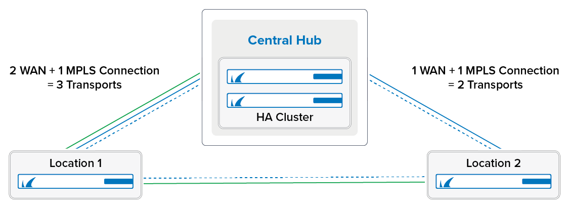
SD-WAN is the logical layer used to manage multiple parallel VPN tunnels (transports) in one VPN tunnel configuration. SD-WAN also handles loadbalancing, fail-over, and traffic routing for all transports of the VPN tunnel.
Without SD-WAN, the VPN tunnel can use the bandwidth of only one of the Internet connections of the CloudGen Firewall. So for firewalls using multiple WAN connections, add an additional transport for each connection to the VPN tunnels. Assign each transport a SD-WAN Classification and SD-WAN ID. When multiple IP addresses are used as Transport Listening IP addresses for one VPN service, the first IP address is always used to create the VPN tunnel. When that IP address is unavailable, the next IP addresses in the list are used until a VPN tunnel can be established. This behavior is undesired if you are using multiple, differently sized WAN connections. Instead, you should assign single, explicit Transport Listening IP addresses to each transport. You thereby know the available bandwidth for the VPN connection and can then assign matching traffic-shaping policies.
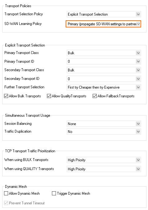
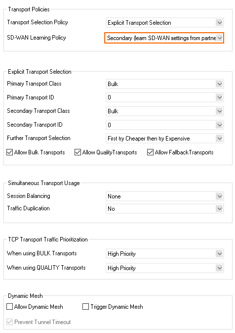
Through the SD-WAN Learning Policy settings you can determine which CloudGen Firewall assigns the VPN transports for the connection (the SD-WAN Primary). To avoid two SD-WAN primaries overriding each other by sending traffic through different transports, the VPN hub must be configured to be the SD-WAN primary while all remote firewalls are configured to be SD-WAN Secondary.
You control which transport is used for a specific connection, with the connection object of the access rule handling the VPN traffic. Configure weighted, session-based load balancing and fallback behavior for your transport. This gives you granular control over which transports and, by extension, which Internet connections are used for the VPN traffic. For example, you can configure your access rules so that VOIP uses an expensive, low-latency connection, whereas large transfers are delegated to the transport running on the cheaper Internet connection.
For more information, see SD-WAN.
Section 5 - Firewall Services and Access Rules
Choosing the Right Firewall Service
Access rules control which traffic is allowed in and out of a VPN tunnel. If you are using a meshed VPN network, you must take into account that traffic originating from every location can be sent through the VPN tunnel. You can reduce the configuration overhead by using the Distributed Firewall service for a cluster of CloudGen Firewall units that share many access rules. Each location can still define specific rules in the Local Rules and Special Rules, but the admin can manage a common set of access rules in the Global Rules. If the CloudGen Firewall units are not in the same cluster or do not share access rules, use a normal Forwarding Firewall service instead. For this example, we are using the Forwarding Firewall service for the central hub and a Distributed Firewall service for all remote locations.
For more information, see Forwarding Firewall and Distributed Firewall.
Access Rule to Allow Traffic in and out of the VPN Tunnels
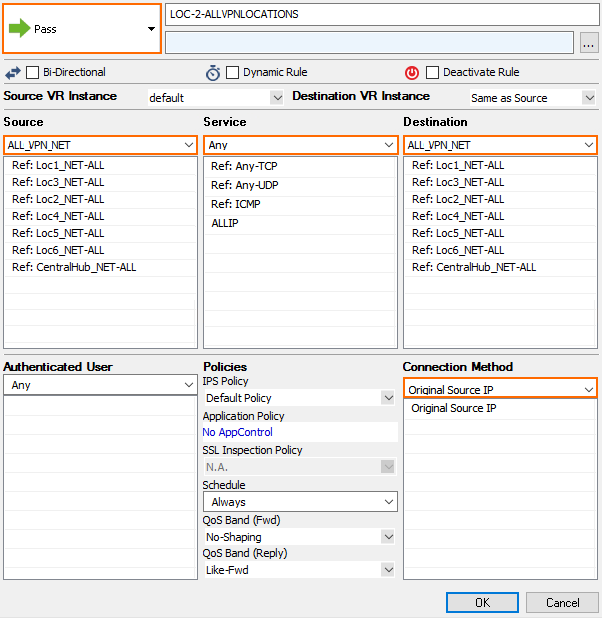
You need to create an access rule to allow traffic in and out of the VPN tunnels. This rule allows transparent access from all networks to all networks. Use this rule to validate that all the VPN networks are accessible and then substitute them with more specific access rules as necessary.
- Action – PASS
- Source – ALL_VPN_NET This is the network object we created containing all the networks in all locations.
- Service – ALL Create a service object containing all services you need to access through the tunnels.
- Destination – ALL_VPN_NET This is the network object we created containing all the networks in all locations.
- Connection Method – Original Source IP Replace with a custom connection object depending on what type of tunnel you want to create (see below).
Using Connection Objects to Hide Networks behind VPN Tunnels
Depending on the connection object used for the access rules allowing traffic in and out of the VPN tunnels, you can:
- Hide all/some remote clients behind one IP address.
- Allow completely transparent network access between the locations.
- Select the transport for SD-WAN with session-based loadbalancing and failover.
For more information, see Examples for TINA VPN Tunnels.
Distributed Firewall Service: Create Access Rules for the Remote Locations
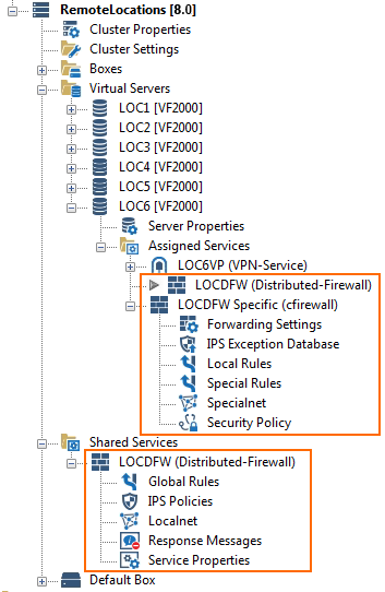
The Distributed Firewall service splits the firewall ruleset into a global ruleset, which is valid for all firewalls using the shared service, and a local and special ruleset. You must create Cascade access rules in the global ruleset for these access rules to be evaluated.
In the Global ruleset, create the following rules:
- Add a Cascade to the local ruleset at the beginning of the global ruleset.
- Add a rule allowing traffic in and out of the VPN tunnels (see above). Use the ALL_NET global network object.
In the Local ruleset, create the following rules:
- Add special rules, e.g., VPN tunnel access rules with custom connection objects, DHCP to VPN service redirect rule for dynamic Internet connections, ...
- Add a Cascade back rule to each local ruleset before the Block All rule.

Special Considerations for CloudGen Firewall Units with a Dynamic Internet Connection
The CloudGen Firewall units using a dynamic Internet connection must redirect all incoming VPN traffic to the VPN service running on the 127.0.0.1 IP address.
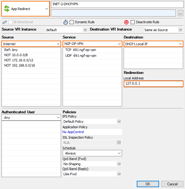
Create an App Redirect access rule to redirect incoming VPN traffic to your VPN service listening on 127.0.0.1
- Action – App Redirect
- Source – Internet
- Service – NG-OP-VPN. If you are using ESP as the transport mode, you must also add ESP to the service.
- Destination – Select the dynamic network object that matches your Internet connection. For example, DHCP-LocalIP for a DHCP Internet connection.
- Redirection – Enter
127.0.0.1.
Section 6 - Additional Topics / Optimizations
Depending on your network and requirements, you can also use the following features to tailor your network to your needs:
Dynamic Mesh
A Dynamic Mesh VPN network allows you to use the advantages of a fully meshed network without having to provide the resources needed for the large number of static VPN tunnels on every unit. All remote units are connected by a static TINA VPN tunnel to a central CloudGen Firewall acting as the VPN hub. When relay traffic from a remote CloudGen Firewall to another remote CloudGen Firewall is detected by the VPN hub, a dynamic VPN tunnel is imitated between the two remote firewalls. As soon as the dynamic VPN tunnel is up, traffic is transparently redirected through the VPN tunnel that now directly connects both locations. The dynamic tunnel is completely transparent to the user and offers better latency than relaying the traffic through the VPN hub. Dynamic tunnels are triggered by the dynamic-mesh-enabled connection object of the VPN hub. Configure the VPN hub as the SD-WAN primary, and the remote units as SD-WAN secondary. The SD-WAN secondaries will automatically learn the Dynamic Mesh and SD-WAN settings from the primary. Traffic that does not match an access rule with a dynamic-mesh-enabled connection object on the SD-WAN primary continues to be sent through the VPN hub.
To use a dynamic mesh instead of a fully meshed network, create Site-to-Site tunnels only between the remote locations and the VPN hub, and use a dynamic-mesh-enabled connection object on the VPN hub to trigger dynamic, on-demand tunnels between the remote locations.
For more information, see Dynamic Mesh VPN Networks.
WAN Optimization
WAN Optimization reduces the amount of traffic sent through the tunnel. You can attain very high deduplication rates depending on the type of traffic going through the tunnel and the amount of available CPU resources. However, WAN Optimization is less effective if you send a lot of UDP or encrypted TCP traffic. Also note that if you rely on SSL Inspection, Virus Scanning, or ATP, these features do not work in combination with WAN Optimization.
For more information, see WAN Optimization.
VPN Compression
If you cannot use WAN Optimization, you can alternatively enable VPN compression to save bandwidth with minimal configuration overhead. VPN compression is not as effective as WAN Optimization, but it can be used in combination with Application Control 2.0.
For more information, see TINA Tunnel Settings.
Traffic Shaping (QoS)
Applying traffic shaping policies to VPN traffic can be configured in two ways, each with its own set of advantages and limitations.
Shape on VPN Transports
Applying shaping policies directly to the VPN transports allows you to shape individual transports. A limitation of this approach is defining optimal inbound and outbound bandwidth settings for systems using multiple transports on one ISP connection is not possible. If the value is set too low, the transport cannot use all the potentially available bandwidth on the network interface. Setting the value too high may cause the available bandwidth of the network interface to be exceeded, causing the traffic shaping engine to drop random VPN packets. This issue does not occur when using consolidated traffic shaping.
Consolidated Traffic Shaping
Consolidated traffic shaping shapes the traffic inside a VPN tunnel with the settings of the network interface used to send the VPN traffic. This lets you define policies to prioritize important traffic if it is sent directly through an interface or is encapsulated into a VPN transport.
Since traffic shaping is applied before either VPN compression or WAN Optimization, using consolidated shaping may result in unused bandwidth on the network interface. This issue does not occur with transport-based traffic shaping because the shaping engine for the physical network interface uses the compressed VPN tunnel packets.
For more information, see Traffic Shaping and How to Apply Traffic Shaping to a VPN Tunnel.

