In cases where SD-WAN cannot handle failover scenarios in your VPN network, use a routed VPN network. A routed VPN network uses the IP addresses assigned to the VPNR interface of the TINA VPN tunnels as gateways. This means that the routing table and the assigned route metrics of the routes determine which tunnel is chosen. When a VPN tunnel goes down, the gateway IP address on the other side of the VPN is no longer reachable, and the route metric for the failing route is automatically increased to 65556. The backup route with the lower metric now matches and redirects the traffic over the failover route to its destination. As soon as the VPN tunnel is back up, the original route becomes available again, and traffic is sent through the direct VPN tunnel again.
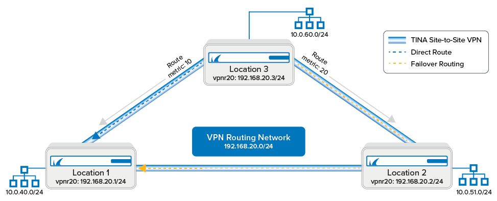
Before You Begin
- A free subnet (e.g.,
192.168.20.0/24) for the intermediary network is needed.
Step 1. Add a VPN Next Hop Interface to Each Firewall
Add a VPN next hop interface using a /24 subnet (e.g., 192.168.20.0/24). Use the same VPNR index for each firewall.
- Go to CONFIGURATION > Configuration Tree > Box > Assigned Services > VPN-Service > VPN Settings.
- Click Lock.
- In the left menu, select Routed VPN.
- Next to the Next Hop Interface Configuration table, click Add.
- In the VPN Interface Properties window, configure the following settings, and then click OK.
- In the VPN Interface Index field, enter a number between
0and999. E.g.,20 - In the IP Addresses field, enter a free IP address for the VPN interface IP address, including the subnet. E.g.,
192.168.20.1/24
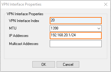
The interface is now listed in the Next Hop Interface Configuration table.
- In the VPN Interface Index field, enter a number between
- Click Send Changes and Activate.
Repeat for each firewall in the VPN network. If possible, use the same VPNR interface index on each firewall.
Step 2. Configure the TINA Site-to-Site VPN Tunnel between the Firewalls
You can configure the VPN tunnels connecting the firewalls using the GTI Editor for managed CloudGen Firewalls, or using the site-to-site configuration dialog if you are using stand-alone CloudGen Firewalls.
In the GTI Editor
Remove the local and remote networks and add the VPN next hop interface ID to the VPN tunnels.
- Go to the global/range/cluster GTI Editor.
- Click Lock.
- Click on the VPN tunnel, and click on the first transport to edit the VPN tunnel configuration. For more information, see How to Create a VPN Tunnel with the VPN GTI Editor.
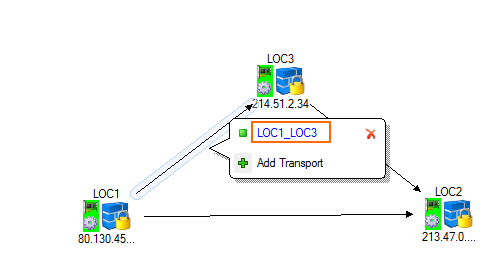
- Verify that the Local Networks for the remote and local VPN services are empty.
- Enter the VPN next hop interface ID for the remote and local VPN services. E.g.,
20
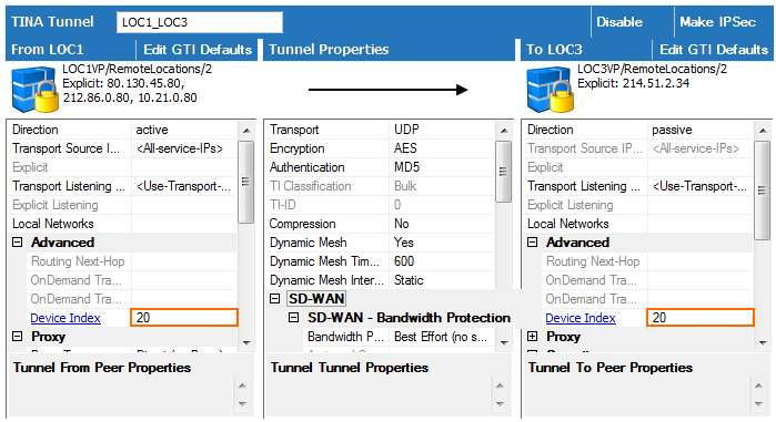
- Click OK.
- Click Send Changes and Activate.
Stand-Alone CloudGen Firewalls
Configure a TINA VPN tunnel using the VPN next hop interface between all firewalls.
- Go to CONFIGURATION > Configuration Tree > Box > Assigned Services > VPN-Service > Site to Site.
- Click Lock.
- Right-click in the TINA Tunnels tab, and select New TINA tunnel. The TINA tunnel window opens.
- Enter a Name.
Configure the Transport, Encryption and Authentication settings as well as the Local and Remote public IP addresses. For more information, see How to Create a TINA VPN Tunnel between CloudGen Firewalls.
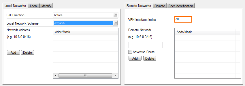
Leave the Local and Remote Network empty.
In the Remote Networks tab, enter the VPN Interface Index number that you created in the VPN Interface Configuration in Step 1. E.g.,
20
- Click OK.
- Click Send Changes and Activate.
Repeat this step until all three firewalls are connected via a TINA Site-to-Site VPN tunnel with each other.
Step 3. Configure Gateway Routes for the Location 1 Firewall
Create the following primary and backup gateway routes on the Location 1 firewall. For more information, see How to Configure Gateway Routes.
- Log into the Location 1 firewall.
- Create a gateway route to Location 3:
- Target Network Address – Enter the Location 3 network in CIDR format:
10.0.60.0/24 - Route Type – Select gateway.
- Gateway – Enter the IP address assigned to the VPNR interface of the Location 3 firewall:
192.168.20.3 - Metric – Enter
10.
- Target Network Address – Enter the Location 3 network in CIDR format:
- Create a gateway route to Location 2:
- Target Network Address – Enter the Location 2 network in CIDR format:
10.0.51.0/24 - Route Type – Select gateway.
- Gateway – Enter the IP address assigned to the VPNR interface of the Location 2 firewall:
192.168.20.2 - Metric – Enter
10.
- Target Network Address – Enter the Location 2 network in CIDR format:
- Create a backup gateway route to Location 3 via Location 2:
- Target Network Address – Enter the Location 3 network in CIDR format:
10.0.60.0/24 - Route Type – Select gateway.
- Gateway – Enter the IP address assigned to the VPNR interface of the Location 3 firewall:
192.168.20.2 - Metric – Enter
20.
- Target Network Address – Enter the Location 3 network in CIDR format:
- Create a backup gateway route to Location2 via Location 3:
- Target Network Address – Enter the Location 3 network in CIDR format:
10.0.51.0/24 - Route Type – Select gateway.
- Gateway – Enter the IP address assigned to the VPNR interface of the Location 3 firewall:
192.168.20.3
- Metric – Enter
20.
- Target Network Address – Enter the Location 3 network in CIDR format:
- Activate the network configuration on the Location 3 firewall. For more information, see How to Activate Network Changes.
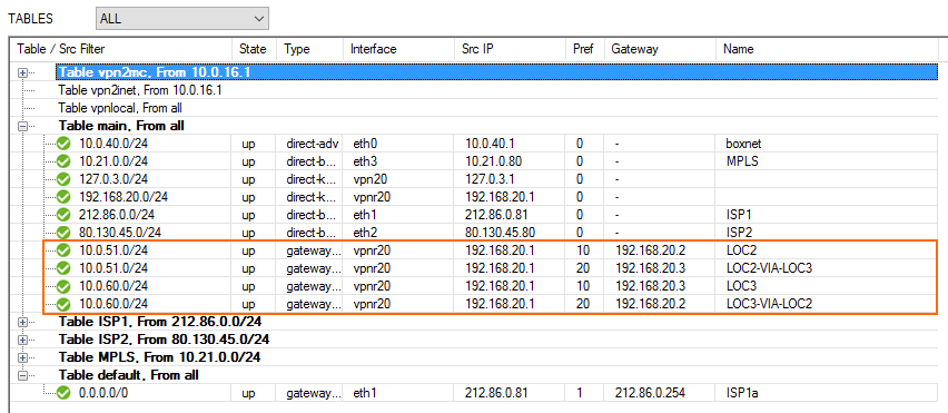
The Location 1 routing table now includes all gateway routes to reach the remote networks with failover routes in case the VPN tunnel goes down.
Step 4. Configure Gateway Routes for the Location 2 Firewall
Create the following primary and backup gateway routes on the Location 1 firewall. For more information, see How to Configure Gateway Routes.
- Log into the Location 2 firewall.
- Create a gateway route to Location 3:
- Target Network Address – Enter the Location 3 network in CIDR format:
10.0.60.0/24 - Route Type – Select gateway.
- Gateway – Enter the IP address assigned to the VPNR interface of the Location 3 firewall:
192.168.20.3 - Metric – Enter
10.
- Target Network Address – Enter the Location 3 network in CIDR format:
- Create a gateway route to Location 1:
- Target Network Address – Enter the Location 2 network in CIDR format:
10.0.15.0/24 - Route Type – Select gateway.
- Gateway – Enter the IP address assigned to the VPNR interface of the Location 2 firewall:
192.168.20.1 - Metric – Enter
10.
- Target Network Address – Enter the Location 2 network in CIDR format:
- Create a backup gateway route to Location 3 via Location 1:
- Target Network Address – Enter the Location 3 network in CIDR format:
10.0.51.0/24 - Route Type – Select gateway.
- Gateway – Enter the IP address assigned to the VPNR interface of the Location 3 firewall:
192.168.20.1 - Metric – Enter
20.
- Target Network Address – Enter the Location 3 network in CIDR format:
- Create a backup gateway route to Location1 via Location 3:
- Target Network Address – Enter the Location 3 network in CIDR format:
10.0.15.0/24 - Route Type – Select gateway.
- Gateway – Enter the IP address assigned to the VPNR interface of the Location 3 firewall:
192.168.20.3
- Metric – Enter
20.
- Target Network Address – Enter the Location 3 network in CIDR format:
- Activate the network configuration on the Location 3 firewall. For more information, see How to Activate Network Changes.
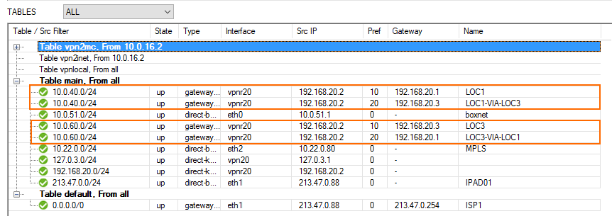
The Location 2 routing table now includes all gateway routes to reach the remote networks with failover routes in case the VPN tunnel goes down.
Step 5. Configure Gateway Routes for the Location 3 Firewall
Create the following primary and backup gateway routes on the Location 3 firewall. For more information, see How to Configure Gateway Routes.
- Log into the Location 3 firewall.
- Create a gateway route to Location 1:
- Target Network Address – Enter the Location 3 network in CIDR format:
10.0.15.0/24 - Route Type – Select gateway.
- Gateway – Enter the IP address assigned to the VPNR interface of the Location 3 firewall:
192.168.20.1 - Metric – Enter
10.
- Target Network Address – Enter the Location 3 network in CIDR format:
- Create a gateway route to Location 2:
- Target Network Address – Enter the Location 2 network in CIDR format:
10.0.51.0/24 - Route Type – Select gateway.
- Gateway – Enter the IP address assigned to the VPNR interface of the Location 2 firewall:
192.168.20.2 - Metric – Enter
10.
- Target Network Address – Enter the Location 2 network in CIDR format:
- Create a backup gateway route to Location 1 via Location 2:
- Target Network Address – Enter the Location 3 network in CIDR format:
10.0.15.0/24 - Route Type – Select gateway.
- Gateway – Enter the IP address assigned to the VPNR interface of the Location 3 firewall:
192.168.20.2 - Metric – Enter
20.
- Target Network Address – Enter the Location 3 network in CIDR format:
- Create a backup gateway route to location 2 via location 1:
- Target Network Address – Enter the Location 3 network in CIDR format:
10.0.51.0/24 - Route Type – Select gateway.
- Gateway – Enter the IP address assigned to the VPNR interface of the Location 3 firewall:
192.168.20.1
- Metric – Enter
20.
- Target Network Address – Enter the Location 3 network in CIDR format:
- Activate the network configuration on the Location 3 firewall. For more information, see How to Activate Network Changes.
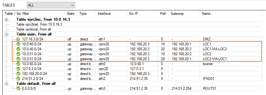
The Location 3 routing table now includes all gateway routes to reach the remote networks with failover routes in case the VPN tunnel goes down.
Monitoring
The VPN tunnels are now monitored like all other gateway routes. When a tunnel goes down, the VPNR interface IP address of the remote firewall is no longer reachable, and the gateway route metric is automatically increased to 65556. Traffic will then use the backup route with the lower metric to reach the destination through the other VPN tunnel. Go to CONTROL > Network to see the routing table.

Go to FIREWALL > Live to see which VPN tunnel is used.

Go to VPN > Status to see if the VPN tunnels are up.

