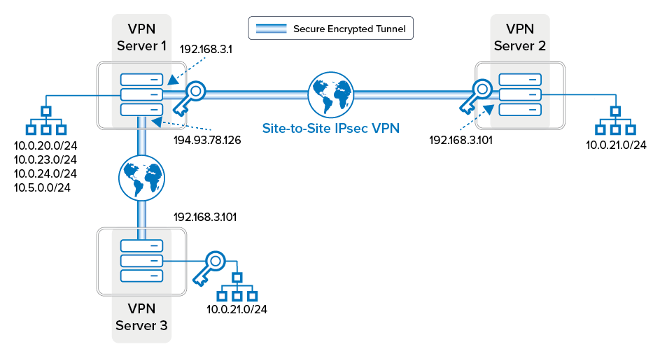
Most real-world VPN topologies comprise a headquarters structure, which means that multiple VPN tunnels terminate on one VPN server. Traffic between outposts is typically routed through the headquarters, thus reducing the number of tunnels to be managed.
The following figure illustrates a star-shaped topology where a VPN connection can be established from 10.0.22.0/24 to 10.0.21.0/24 without the need to configure a tunnel between VPN servers 2 and 3.
Star-Shaped Topology with One HQ and Two Outposts:

The following table illustrates the relationship between the local and partner networks:
| Tunnel | VPN Server | Local Network | Partner Network |
|---|---|---|---|
| Tunnel 1 - 2 | Server 1 | 10.0.0.0/8 | 10.0.21.0/24 |
| Server 2 | 10.0.21.0/24 | 10.0.0.0/8 | |
| Tunnel 1 - 3 | Server 1 | 10.0.0.0/8 | 10.0.22.0/24 |
| Server 3 | 10.0.22.0/24 | 10.0.0.0/8 |
Redirection of traffic for VPN networks to the VPN server engine is usually handled through a policy routing table introduced by the VPN server. However, this policy routing table will not work properly if the local network is part of the partner network, as shown in the example figure. In this case, traffic originating from the local network itself would be rerouted incorrectly into the VPN engine. This condition can be circumvented by introducing a throw route, which explicitly excludes the local network from the policy routing table.
