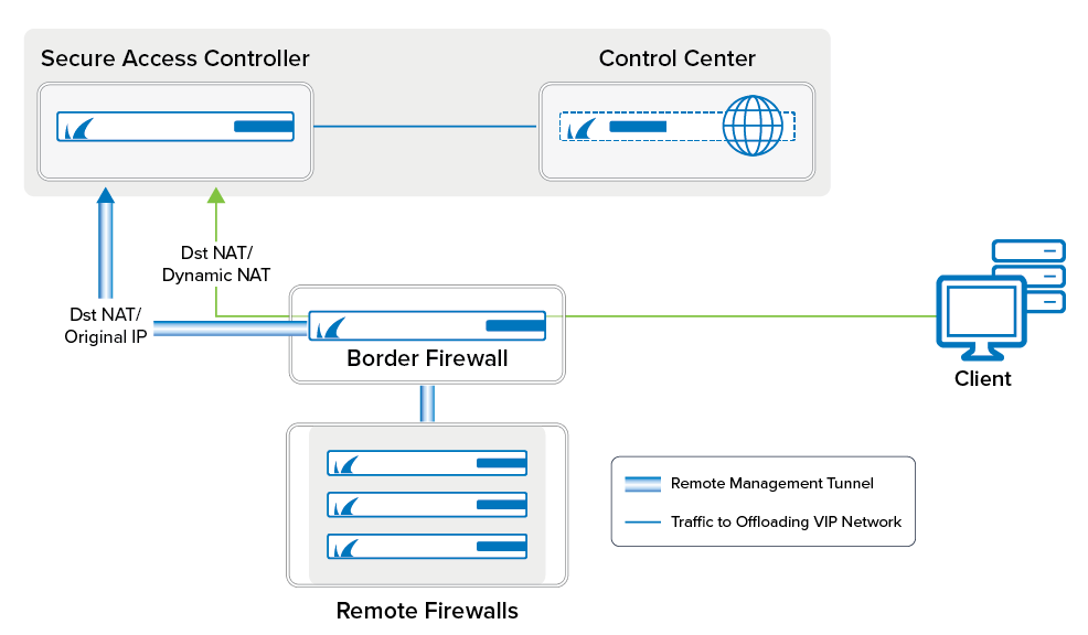
For large deployments, you can reduce the load on the Control Center by configuring one or more Secure Access Controllers (VACC) to handle the remote management tunnels. The VACC must be managed by the Control Center and be in the same subnet as the Control Center.
Before You Begin
- Deploy a Secure Access Controller. Note: The Access Controller must be managed by the Control Center.
- Assign a free network to be used as the VIP network.
- Remove the VIP networks to be offloaded from the Control Center.
Step 1. Deploy a CloudGen Firewall Image to Be Used as the VACC
Deploy a virtual or public cloud CloudGen Firewall. Verify that the number of CPU cores, storage, and RAM are sized according to your VACC model. If your VACC is deployed in Azure or AWS, see Secure Access Controller in Azure and AWS for more information on how to integrate the VACC with your existing cloud resources.
Barracuda Secure Connector | Model | Number of Licensed Cores | Minimum Storage [GB] | Minimum Memory [GB] |
|---|---|---|---|---|
| SC 400 | VACC400 | 2 | 80 | 2 |
SC 600 | VACC610 | 4 | 80 | 2 |
| SC 800 | VACC820 | 8 | 80 | 2 |
For more information, see Virtual Systems (Vx), Microsoft Azure Deployment, Amazon AWS Deployment
Step 2. Import the VACC Into the Control Center
The VACC must be managed by the same Control Center that is managing the CloudGen Firewalls.
For more information, see How to Import an Existing CloudGen Firewall into a Control Center.
Step 3. License the Secure Access Controller
License and activate the VACC using Barracuda Activation on the Control Center. The licenses are automatically downloaded and assigned to the VACC. Go to your VACC > Box Licenses and verify that the licenses are installed.
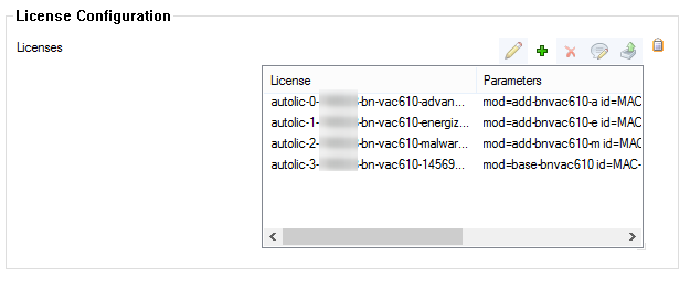
For more information, see How to Assign and Activate Single Licenses on a Control Center.
Step 4. Create the VACC VPN Service
Create the Access Controller VPN service.
- Go to your Cluster > Assigned Services .
- Right-click Assigned Services and select Create Service.
- Enter a Service Name. The name must be unique and no longer than six characters. The service name cannot be changed later.
- From the Software Module list, select VPN Access Controller .

- (optional) Change the Service IPs. For more information, see How to Assign Services.
- Click Finish.
- Click Activate.
Step 5. Add VIP Networks to the Access Controller
Add the VIP network to the Access Controller.
Go to Assigned Services > VPNAC > SAC VPN Settings.
- Click Lock.
- Click + to add a VIP Network. The VIP Networks window opens.
- Enter a Name and click OK.
- Enter the network address of the VIP network in Network Address. E.g.,
10.0.16.0 - Select the Netmask. E.g., 24-bit
- Click OK.
- Click Send Changes and Activate.
Step 6. Configure an Access Rule to Allow Traffic to the Control Center
Create an access rule allowing management traffic to and from the Access Controller to the Control Center.
- Go to CONFIGURATION > Configuration Tree > your Access Controller > Assigned Services > Firewall > Forwarding Rules.
- Click OK.
- Right-click in the ruleset and click New and Rule in the context menu.
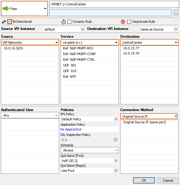
- Create the following access rule:
- Action – Select Pass.
- Name – Enter a name.
- Bi-Directional – Enable Bi-Directional.
- Source – Select a network object containing the offloaded VIP networks.
- Service – Select Explicit and add NGF-MGMT-BOX, NGF-MGMT-CONF, NGF-MGMT-CTRL, NTP, UDP Port 801, UDP Port 810 and authentication services as needed (E.g., LDAP).
- Destination – Select a network object containing both the box level and CC level IP address of the Control Center.
- Connection Method – Select Original Source IP.
- Click OK.
- Click Send Changes and Activate.
Step 7. Create a Gateway Route on the Box Level of the Control Center
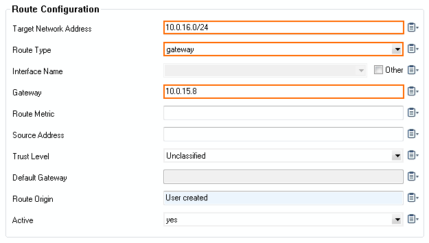
If the Control Center and the SAC are in the same subnet, you must create a gateway route for the VIP network using the IP address the VPNAC is listening on as the gateway. If the SAC can be reached via the default gateway of the Control Center, the gateway route is not needed.
Add a gateway route to the VIP network and activate the network changes:
- Target Network Address – Enter the VIP network. E.g.,
10.0.16.0/24 - Route Type – Select gateway.
- Gateway – Enter the IP address the VPNAC service is listening on.
For more information, see How to Configure Gateway Routes.
Step 8. Configure a Gateway Route and Access Rules on the Border Firewall
If the border firewall also acts as the default gateway in your network, create a gateway route for the VIP network and an access rule to allow traffic to the VIP network. The second access rule redirects incoming management tunnel traffic from the remote CloudGen Firewalls to the Access Controller.
Step 8.1 Add a Gateway Route
Add a gateway route to the VIP network and activate the network changes:
- Target Network Address – Enter the VIP network. E.g.,
10.0.16.0/24 - Route Type – Select gateway.
- Gateway – Enter the IP address the VPNAC service is listening on.

For more information, see How to Configure Gateway Routes.
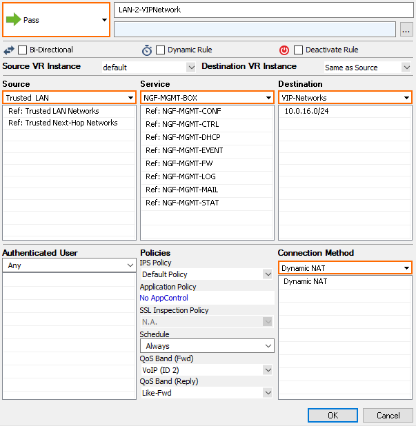
Step 8.2. Add an Access Rule to Allow Traffic to the VIP Network
Create an access rule to allow traffic from the LAN to the VIP network:
- Action – Select Pass.
- Name – Enter a name.
- Source – Select Trusted Network.
- Service – Select all services you need to access on the remote CloudGen Firewall.
- Destination – Enter the VIP network. E.g.,
10.0.16.0/24 - Connection Method – Select Dynamic NAT.
Step 8.3 Add a Dst NAT Access Rule for Incoming MGMT Tunnel Traffic
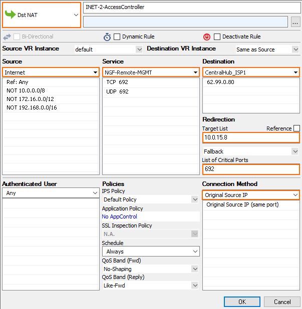
Incoming management tunnel traffic must be redirected to the Access Controller.
- Action – Select Dst NAT.
- Name – Enter a name.
- Source – Select Internet.
- Service – Select Explicit and add a service entry for TCP traffic on port 692.
- Destination – Select Service IPs.
- Target List – Enter the IP address the CC-VPN service is listening on.
- List of Critical Ports – Enter
692. - Connection Method – Select Original IP.
Step 8.4. Add an Access Rule on the Access Controller to Allow Traffic to the VIP Network
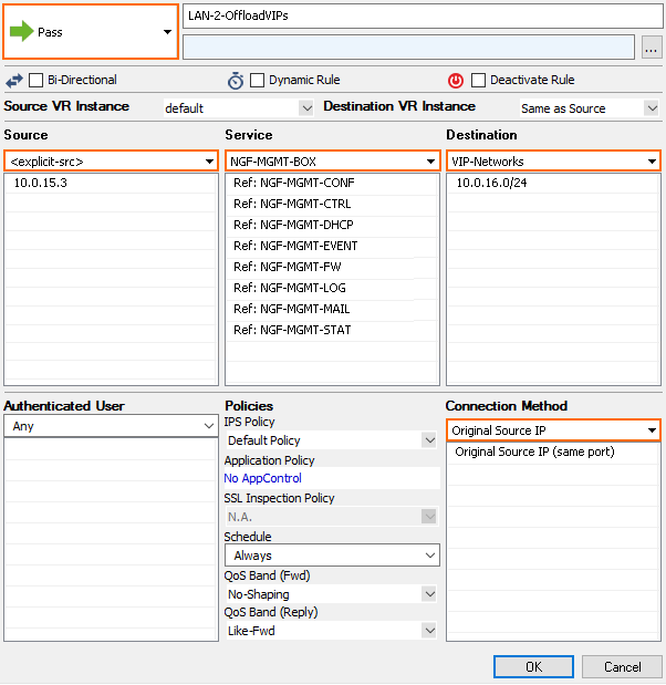
Create an access rule to allow traffic from the IP address of the border firewall to the VIP networks:
- Action – Select Pass.
- Name – Enter a name.
- Source – Enter the IP address of the border firewall.
- Service – Select NGF-MGMT-BOX.
- Destination – Enter the VIP network. E.g.,
10.0.16.0/24 - Connection Method – Select Original IP.
Troubleshooting
- If the remote CloudGen Firewalls are not connecting to the Firewall Control Center, verify that you can ping the VIP assigned to the firewall from the Control Center box level. It may take some time for the CloudGen Firewall to be on the Status Map of the Control Center.
- Verify that the IP address of the border firewall routing the VIP network traffic to the Access Controller is listed as a Remote Network of the remote management tunnel. If this IP address is missing, traffic will not be sent through the remote management tunnel.
- Depending on the number of managed firewalls, exporting the PAR file for the Access Controller can take some time.
