Virtual routers forward traffic like physical routers. Because they are virtual, these routers can be configured and activated on demand without the need of using a separate hardware device. Each virtual router uses its own routing and forwarding table. The routing and forwarding table describes the path between multiple interfaces that packets travel through.
The following example demonstrates how to connect a private network (e.g., a classroom) that gets access to the Internet via a virtual router. The private network will be connected on interface eth2, the Internet to the interface eth3. In this setup, the firewall service will be transparent to the additional virtual router instance only if authenticated users are not defined. All other services are not available to the additional virtual router. For more information on which services are available for additional virtual instances, see Virtual Routing and Forwarding (VRF).
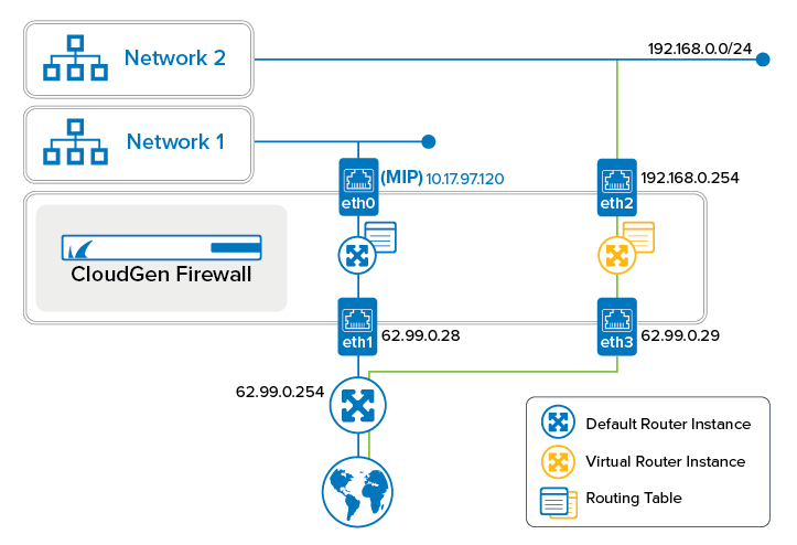
Step 1. Create a Virtual Router Node
- Go to CONFIGURATION > Configuration Tree > Box.
- Right-click Network.
- From the menu, select Lock.
- (optional) In case the firewall is a CC-managed appliance:
- The window for Emergency Override is displayed.
- Click OK if you want to override the configuration provided by the Control Center.
- From the menu, select Create Virtual Router Instance.
- The window for naming the virtual router is displayed.
- Enter the name for the virtual router, e.g.,
VR01. - Click OK.
- In the ribbon bar, click Activate.
- The Activate Changes window opens.
- Click Activate.
- The virtual router node is displayed one hierarchy level below Network.
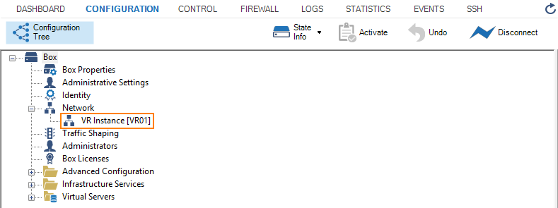
Step 2. Create the Virtual Router and Assign Required Interfaces (Hardware, Virtual, VLAN, and Bundled Interfaces)
Before the creation of a virtual router, all interfaces are assigned to the 'default' router.
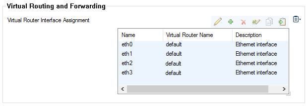
- Go to CONFIGURATION > Configuration Tree > Box > Network.
- In the left menu, select Virtual Router.
- Click Lock.
- In the list, double-click the entry with the interface that you want to assign to the virtual router node, e.g., eth2 to VR01.
- The Virtual Router Interface Assignment window is displayed.
- From Virtual Router Name, select your virtual router, e.g., VR01.

- Click OK.
- (optional) In case you want to assign further interfaces, repeat the previous four steps.
- Click Send Changes.
- Click Activate.
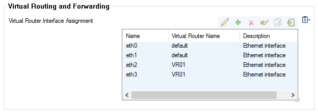
Step 3. Activate the New Network Configuration
After assigning interfaces to the virtual router, the network must be re-activated with the new interface assignment.
- Go to CONTROL > Box.
- In the left menu, click Network to expand the menu.
- Click Activate new network configuration.
- The Network Activation window is displayed.
- Click Failsafe.
Step 4. Configure Network/IP Addresses
The new virtual router needs to know which IP address(es) is/are assigned to which interface(s) and define the network path, e.g., the path from the classroom to the Internet.
- Go to CONFIGURATION > Configuration Tree > Box.
- In case your virtual router node is not displayed, click the + to the left of the node Network.
- Double-click VR Instance [ your virtual router ].
The newly created VR instance is displayed showing the state and the ID of the instance.

- Click Lock.
- From the left menu, select IP Configuration.
- In the IPv4 Addresses section, click +.
- The IPv4 Addresses window opens.
- Enter the name for the IP address, e.g., VR01-to-Classroom1. The IP Address Configuration window opens.
- Interface Name – Select the interface that will be managed by the virtual router, e.g., eth2.
- IP Address – Enter the IP address that must be assigned to the interface, e.g.,
192.168.0.1 - Associated Netmask – Select the size of the netmask from the list, e.g., 24-bit.
- Responds to Ping – Select yes in case you want the interface to respond to ICMP ping packets.
- Click OK.
- Repeat all steps beginning with Step 7 for the IP address that will be connected to the Internet, e.g., VR01-to-INTERNET, eth3, 62.99.0.29.
- Click Send Changes.
- Click Activate.

Step 5. Configure the Routing Table
Configure all routes according to your needs. In this example, a default route is added to the routing table of VR01.
- Go to CONFIGURATION > Configuration Tree > Box > Network > VR Instance [ your virtual router ].
- In the left menu, click Routing.
- Click Lock.
- In the IPv4 Routing Table section, click +.
- The IPv4 Routing Table window is displayed.
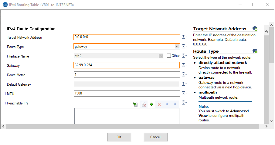
- Enter the name for the new routing table entry, e.g., VR01-to-INTERNET. The window for the Route Configuration is displayed.
- Target Network Address – Enter the IP address of the destination network, e.g.
0.0.0.0/0 - Route Type – Select gateway.
- Gateway – Enter the IP address to the gateway, e.g.,
62.99.0.254
- Target Network Address – Enter the IP address of the destination network, e.g.
- Click OK.
- Click Send Changes and Activate.
Step 6. Verify the New Network Configuration
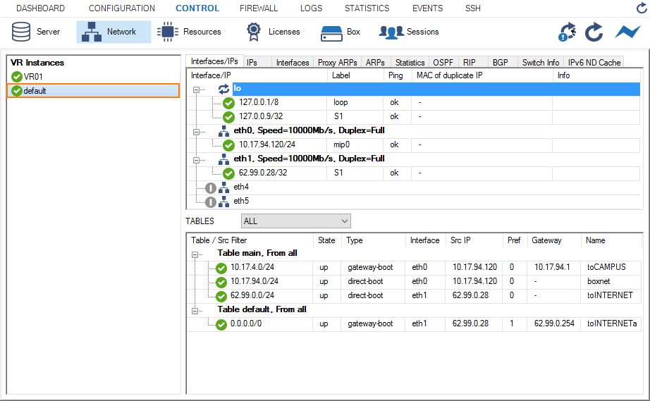
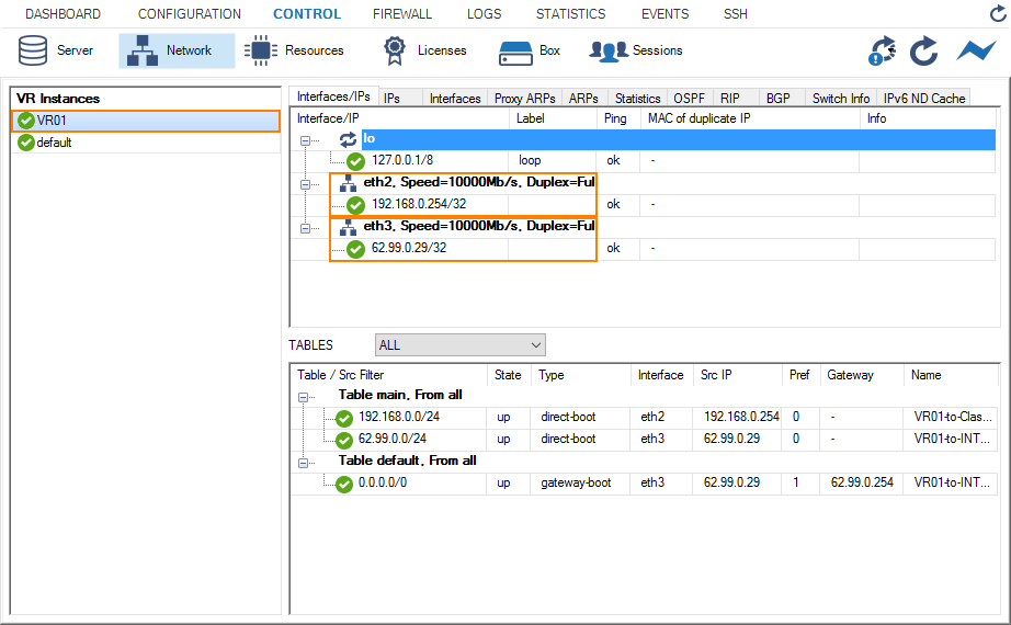
- Go to CONTROL > Network.
- In the left column, select default to display the network settings for the default router.
- In the left column, select VR01 to display the network setting for the virtual router VR01.
Step 7. Create an Access Rule for the Newly Created Virtual Router VR01
To pass traffic from interface eth2 (192.168.0.254/32) to eth3 (62.99.0.29/32), create an access rule and constrain the access rule to the virtual router VR01.
- Go to CONFIGURATION > Configuration Tree > Assigned Services > NGFW (Firewall) > Forwarding Rules.
- Click Lock.
- Click + to add an access rule.
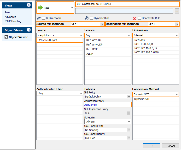
- For the access rule type, select Pass.
- Enter a name for the access rule. For a better differentiation between rules that apply to the default router instance and a better overview, it is recommended to prepend a prefix like 'VRF' or 'VR01' to the name of the access rule, e.g., VRF-Classroom-to-INTERNET.
- Source VR Instance – Select the name of the virtual router instance that you created in Step 1.
- Destination VR Instance – Select the name of the virtual router instance that you created in Step 1.
- Source – Enter the IP address of the source network, e.g.,
192.168.0.0/24. - Service – Select Any.
- Destination – Enter the IP address for the Internet from the list.
- Application Policy – In case you have licensed Application Control, you can activate it now.
- Connection Method – Select Dynamic NAT.
- Click OK.
- Click Send Changes and Activate.
Step 8. Activate Columns to Display the Traffic Flow Through Your Virtual Router Instance
- Go to FIREWALL > Live.
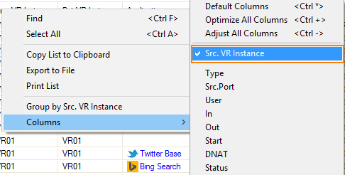
- Right-click on any of the column identifiers of the Live view.
- From the menu, select Columns -> Src. VR Instance.
- Right-click on any of the column identifiers of the Live view.
- From the menu, select Columns -> Dst. VR Instance.
Step 9. Verify that Traffic is Flowing from the Source Network to the Internet
Set up a client with an IP address in the source network (e.g., 192.168.0.1) and set the default route on the client to the address of the virtual router, e.g., 192.168.0.254.
- On your client, open a web browser and go to a website of your choice, e.g., www.nytimes.com
- Go to FIREWALL > Live.
- The Live view will display a mix of traffic flowing both through the default router and the virtual router you configured before, e.g., VR01.
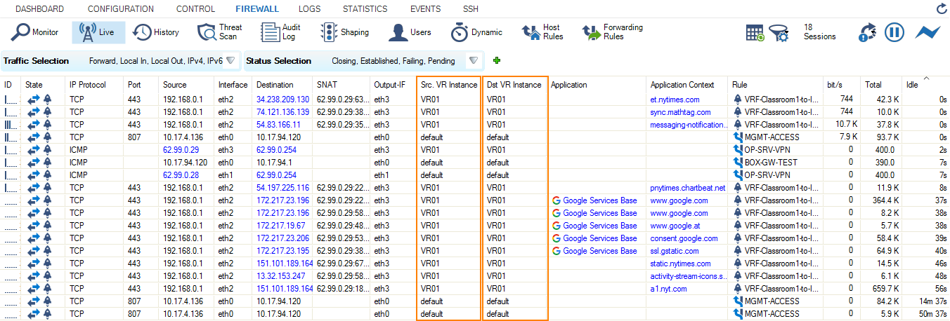
- In order to restrict display output only to the URL you entered before, activate a display filter for the virtual router instance by clicking on the filter symbol in any of the lines showing VR01.

