To successfully create a Named Network object, you must carefully plan your Named Network structure because it cannot be edited after it has been created. Groups and values must then be added to the structure to properly represent your network. Values can represent single networks, multiple networks, sequential networks, or non-sequential networks. They can also be used as placeholders by creating empty containers.
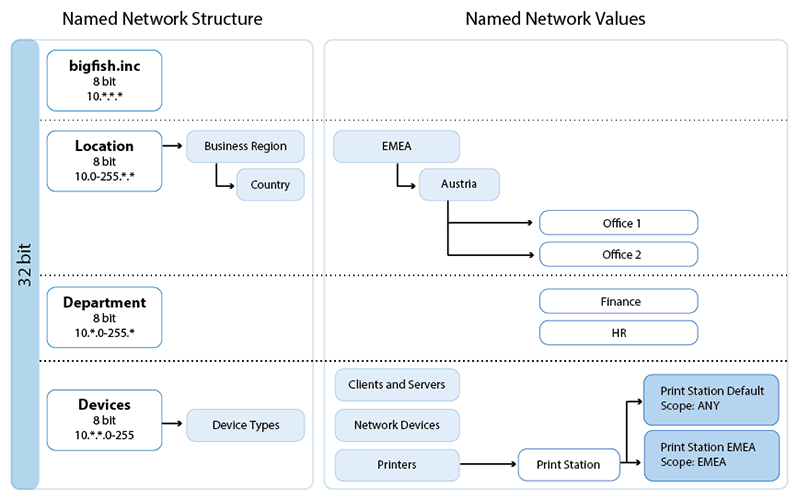
Named Network Objects on the Firewall Control Center
Named Network objects can also be created in the Global, Range, and Cluster Firewall Objects. For cluster and range Named Network objects, the Own Firewall Objects must be enabled in the Cluster or Range Properties.
Before You Begin
- Verify that the feature level is 7.2. or above. For more information, see How to Manage Ranges and Clusters.
Step 1. Configure Named Network Structure
Enter the scope and value for the static bits. The scope always starts with the first bit of the 32-bit IPv4 address. E.g., 8 for 10.*.*.* or 16 for 192.168.*.* The Named Network structure cannot be changed after this window is closed.
- Go to CONFIGURATION > Configuration Tree > Box > Assigned Services > Firewall > Forwarding Rules.
- Click Lock.
- In the left menu, click Named Networks.
- Right-click in the main area and select New Named Network Object, or click + on the top right of the main area. The Create Named Network window opens.

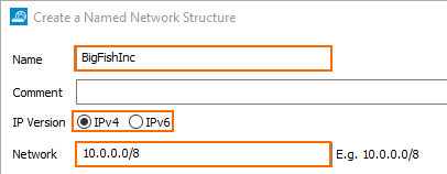
- Configure the root Named Network tree nodes to reserve the first X static bits:
- Name – Enter the name for the Named Network.
- IP Version – Select the IP version.
- Network – Enter the network covered by this Named Network structure in CIDR format. E.g.,
10.0.0.0/8
- In the Named Network Structure table, click + to create a Named Network tree node. A new line section is added to the Named Network Structure table.

- Configure the Named Network tree node:
- Name – Click the mouse-over edit button and enter the name for the Named Network tree node. Use category names, not values. E.g., "Location" not "EMEA".
- Bits – Click the mouse-over edit button and enter the scope for this tree node.
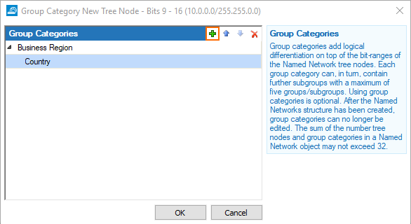
- (optional) Click the mouse-over edit button in the Group Category column. The Group Category window opens.

- (optional) Click + to add up to five Group categories and click OK.
- Configure the next Named Network tree node until the full scope has been assigned.

- Verify that the number of tree nodes added to the number of group categories does not exceed 32.
- Double-check your Named Network structure. The structure cannot be changed after it is created.
- Click Save.
- Click Send Changes and Activate.
The Named Network structure is now displayed.

Step 2. Create Groups in Group Categories
Add groups to the group categories. Check the Scope column to see the group categories for a Named Network tree node.
- Go to CONFIGURATION > Configuration Tree > Box > Assigned Services > Firewall > Forwarding Rules.
- Click Lock.
- In the left menu, click Named Networks.
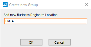
- Right-click a Named Network tree node and select Add new group_category_name to tree_node_name. The Create new Group window opens.

- Enter the name for the new group in this category.
- Repeat for the other groups in this group category.

- If group subcategories exist, right-click a group and select Add new group_subcategory to tree_node .

- Enter the name for the group in the group sub-category.
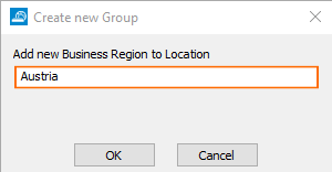
- Click OK.
- Repeat for all subcategories and add groups to each group subcategory.
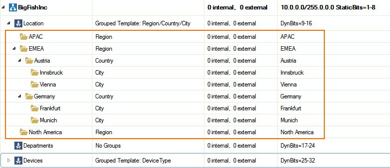
- Repeat for all Named Network tree nodes with group categories.
- Click Send Changes and Activate.
The Named Network structure and all groups and subgroups are now filled in.
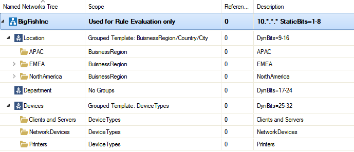
Step 3. Add Values to Named Network Structure
Named Network values can be used in varying ways:
- Named Network value for one or multiple sequential networks
- Named Network value containers for multiple non-sequential networks
Named Network value containers with sub-values in different scopes
Named Network Value for One or Multiple Sequential Networks
Network values are added either to the Named Network tree node, or, if groups are configured, to the lowest group in the Named Network tree structure.
- Go to CONFIGURATION > Configuration Tree > Box > Assigned Services > Firewall > Forwarding Rules.
- Click Lock.
- In the left menu, click Named Networks.
- Right-click a Named Network tree node or Named Network group, whichever is the lowest in the tree structure, and select Add new Value to name_of_group .

- Configure the Named Network value:
- Value – Select the value from the drop-down list. Only values matching the scope of the Named Network tree node are displayed.
- Number of Addresses – Enter the number of addresses to include in this network. Enter
1if one network is assigned
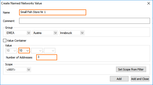
- Click Add and Close.
- Click Send Changes and Activate.
The value is now listed in the Named Network structure.

Named Network Value Containers for Multiple Non-Sequential Networks
Value containers form a group for multiple Named Network values with different scopes or multiple non-sequential networks. For example, one store location uses 10.13-16.*.* and 10.45-47.*.* as network. Since the networks are not sequential, two sub-values are needed to describe the Named Network value for this store.
- Go to CONFIGURATION > Configuration Tree > Box > Assigned Services > Firewall > Forwarding Rules.
- Click Lock.
- In the left menu, click Named Networks.
- Right-click a Named Network tree node or Named Network group, whichever is the lowest in the tree structure, and select Add new Value to name_of_group .
- Enter a Name
- Select the Value Container check box.
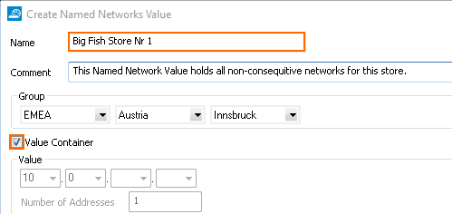
- Click Add and Close.
- Right-click the value container and select Add Subvalue to name_of_value_container .
- Add additional sub-values to the tree node:
- Value – Select the value from the drop-down list. Values that are outside of the scope of the tree nodes are grayed out.
- Number of Addresses – Enter the number of addresses starting from the the selected value. Enter
1to use only the selected value. - Scope – Select a scope.
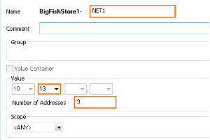
- Click Add.
- Configure the sub-value for the Named Network value container with scope of Any.
- Value – Select the value from the drop-down list. Values that are outside of the scope of the tree nodes are grayed out.
- Number of Addresses – Enter the number of addresses starting from the the selected value. Enter
1to use only the selected value. - Scope – Select a scope.
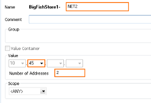
- Click Add and Close.
- Click Send Changes and Activate.
The Named Network value with sub-values is now displayed in the Named Network tree.

Named Network Value Containers with Sub-Values in Different Scopes
In this example, a value container with two sub-values is created. One sub-value uses a more specific scope, the other a scope of ANY. Use, for example, to describe a setup in which the printer always uses the IP address *.*.*.100 except in one region where *.*.*.111 is used.
- Go to CONFIGURATION > Configuration Tree > Box > Assigned Services > Firewall > Forwarding Rules.
- Click Lock.
- In the left menu, click Named Networks.
- Right-click a Named Network tree node or Named Network group, whichever is the lowest in the tree structure, and select Add new Value to name_of_group .
- Enter a Name and select the Value Container check box.
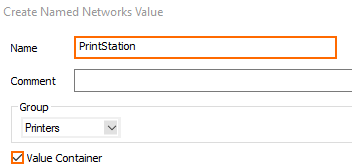
- Click Add and Close
- Right-click the value container and select Add Subvalue to name_of_value_container .

- Add additional sub-values to the tree node:
- Value – Select the value from the drop-down list. Values that are outside of the scope of the tree nodes are grayed out.
- Number of Addresses – Enter the number of addresses starting from the the selected value. Enter
1to use only the selected value. - Scope – Select <ANY>.
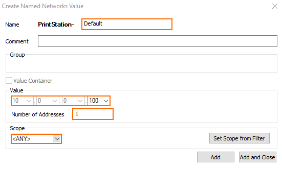
- Configure the sub-value for the Named Network value container with scope of Any.
- Value – Select the value from the drop-down list. Values that are outside of the scope of the tree nodes are grayed out.
- Number of Addresses – Enter the number of addresses starting from the the selected value. Enter
1to use only the selected value. - Scope – Select the groups and subgroups that this value is valid for.
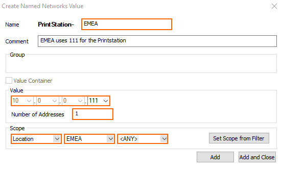
- Click Add and Close.
- Click Send Changes and Activate.

Step 4. Set for Scope for Named Network Objects
Named Network objects can be used only for firewall ruleset evaluation or for ruleset evaluation and visualization on the FIREWALL > Live and FIREWALL > History pages. For Named Network objects created in the global, range, or cluster firewall objects, this has to be configured directly in the firewall service individually using the network objects.
- Go to CONFIGURATION > Configuration Tree > Box > Assigned Services > Firewall > Forwarding Rules.
- Click Lock.
- In the left menu, click Named Networks.
- Right-click the root tree element of the Named Network object and select Used for Rule Evaluation and Visualization.

- Click Send Changes and Activate.
You can now configure network objects to use Named Network objects and add the Src and Dst Named Networks columns to the FIREWALL > Live and FIREWALL > History pages.
