If you are using the Amazon Virtual Private Cloud, you can transparently extend your local network to the cloud by connecting the private networks through a site-to-site IKEv1 IPsec VPN tunnel. The Amazon virtual private gateway uses two parallel IKEv1 IPsec tunnels to ensure constant connectivity. The subnets behind the VPN gateway are propagated via BGP.

Before You Begin
Create an Amazon Virtual Private Cloud (VPC).
- Create at least one subnet in the VPC.
- Create and configure the Amazon Routing Table.
- The security group of the VPC must allow the desired connections. For more information, see https://docs.aws.amazon.com/en_pv/vpn/latest/s2svpn/SetUpVPNConnections.html#vpn-configure-security-groups.
- On your CloudGen Firewall, create the VPN service if it does not already exist.
Configure the VPN Service Listeners.
- Create the OPSF/RIP/BGP service if it does not already exist.
Step 1 - Create the Amazon VPN Gateway
Step 1.1 - Create a Virtual Private Gateway
The Amazon virtual private gateway is the VPN concentrator on the remote side of the IPsec VPN connection.
- Go to the Amazon VPC Management Console.
- In the left menu, click Virtual private gateways.
- Click Create virtual private gateway.

- Enter the Name tag for the VPN gateway (e.g.,
Campus Virtual Private Gateway). - Click Create virtual private gateway.
- Select the newly created virtual private gateway, click Actions and select Attach to VPC.
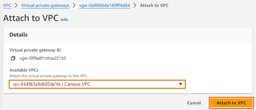
- Select your VPC from the VPC list, and click Attach to VPC.
The virtual private gateway is now available.

Step 1.2 - Add Your Customer Gateway Configuration
The Amazon customer gateway is your Barracuda CloudGen Firewall on your end of the VPN connection. Specify your external IP address and routing type in the customer gateway configuration:
- Go to the Amazon VPC Management Console.
- In the left menu, click Customer gateways.
- Click Create customer gateway.
- Enter the connection information for your firewall:
- Name tag – Define a name tag for your device (e.g.,
My Barracuda CloudGen Firewall). - BGP ASN – Enter your BGP ASN number.
- IP address – Enter your external IP address. To look up the external IP address, go to CONTROL > Network.
- Device – Enter a name for your device (e.g.,
FW-appliance).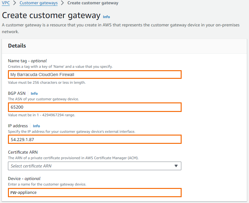
- Name tag – Define a name tag for your device (e.g.,
- Click Create Customer Gateway.
Your firewall is now registered in the AWS cloud and you can configure VPN connections.
Step 1.3 - Create a VPN Connection
Create a VPN connection with the Customer Gateway (Your CloudGen Firewall) and the Amazon Virtual Private Gateway that you just created. Then download the VPN configuration file that contains all necessary information for configuring the VPN connection on the firewall.
- Go to the Amazon VPC Management Console.
- In the left menu, click Site-to-Site VPN connections.
- Click Create VPN connection.
- In the Create VPN connection window, enter the configuration information for your VPN connection:
- Name tag – Enter a name for your VPN connection (e.g., CGF
2AWSCloud). - Virtual Private Gateway – Select the virtual private gateway created in Step 1.
- Customer Gateway – Select the customer gateway created in Step 1.
- Routing Options – Select Dynamic (requires BGP).
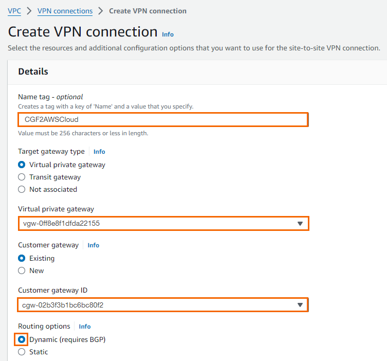
- Name tag – Enter a name for your VPN connection (e.g., CGF
- Click Create VPN connection.
- Once the connection is available in AWS, click Download configuration.
- Select generic vendor and platform settings for the configuration file:
- Vendor – Select Generic.
- Platform – Select Generic.
- Software – Select Vendor Agnostic.
- IKE version – Select ikev1.
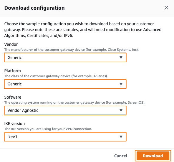
Click Download, and save the
vpn-<YOUR-VPC-ID>.txtfile. The configuration file contains all required information to configure each VPN tunnel and the respective BGP routing options on your CloudGen Firewall.
Step 1.4 - Enable Route Propagation
- Go to the Amazon VPC Management Console.
- In the left menu, click Route tables.
- Select the route table attached to your VPC used in Step 1.1.
- Click Route propagation.

- Click Edit Route Propagation.

- Enable the route propagation for your virtual private gateway created in Step 1.1 by selecting the check box next to it.
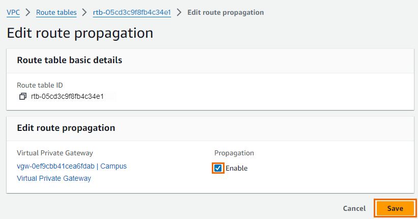
- Click Save.
Step 2 - Configure IPsec Tunnels on the Barracuda CloudGen Firewall
For each IPsec tunnel, create a next-hop interface and then configure two IPsec site-to-site VPN tunnel. Use the IP addresses provided in the Amazon generic VPN configuration file you downloaded at the end of Step 1.
Step 2.1 - Create VPN Next-Hop Interfaces
For each IPsec tunnel, a VPN next-hop interface must be created. Use the IP addresses provided in the Amazon generic VPN configuration file you downloaded at the end of Step 1.
- Go to CONFIGURATION > Configuration Tree > Box > Assigned Services > VPN-Service > VPN Settings.
- Click Lock.
- In the left navigation bar, click Routed VPN.
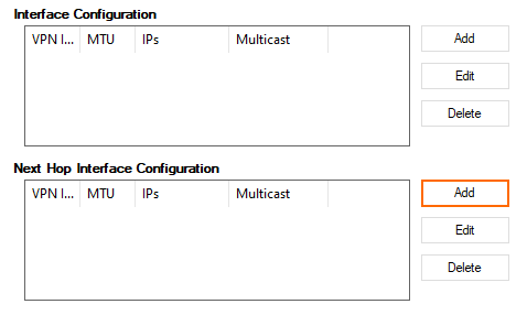
- Create a VPN next-hop interface for each IPsec tunnel by clicking Add in the VPN Next Hop Interface Configuration section.
- In the VPN Interface Properties window enter:
- VPN Interface Index – Enter a number between 0 and 99. Each interface index number must be unique. E.g., IPsec tunnel1:
10and IPsec tunnel:11 - MTU – Enter
1436. - IP Addresses – Enter the Inside IP Address of the Customer Gateway provided by Amazon. E.g., IPsec tunnel1:
169.254.254.58/30, IPsec tunnel 2:169.254.254.62/30
- VPN Interface Index – Enter a number between 0 and 99. Each interface index number must be unique. E.g., IPsec tunnel1:
- Click OK.
- In the VPN Interface Properties window enter:
- (optional) In the left navigation bar, click IPSec. Enable Use IPSec dynamic IPs if you are using a dynamic WAN IP address. This will create an IPsec VPN listener on 0.0.0.0/0.
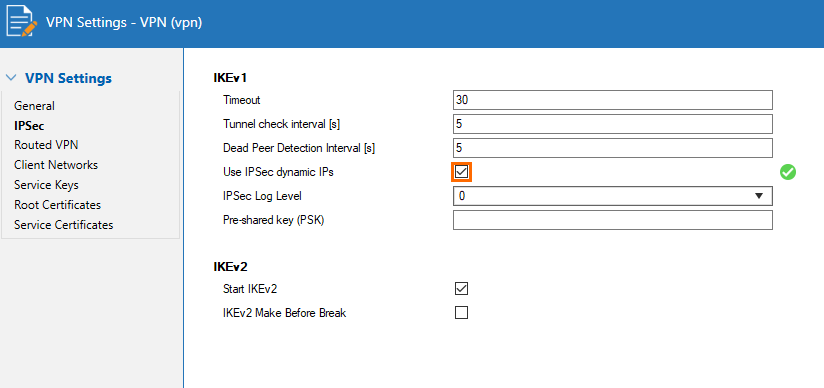
- Click Send Changes and Activate.
Step 2.2. Configure Two Site-to-Site IPsec Tunnels
Configure two site-to-site IPsec tunnels using the VPN next-hop interfaces. Make sure to use the correct IP addresses and corresponding next-hop interfaces listed in the Amazon generic VPN configuration file for each tunnel.
- Go to CONFIGURATION > Configuration Tree > Box > Assigned Services > VPN-Service > Site to Site.
- Click on the IPSEC IKEv1 Tunnels tab.
- Click Lock.
- For each IPsec tunnel, right-click and click New IPsec IKEv1 tunnel.
- Enter the IPsec tunnel configurations:
- Enter a Name. E.g, IPsec Tunnel 1:
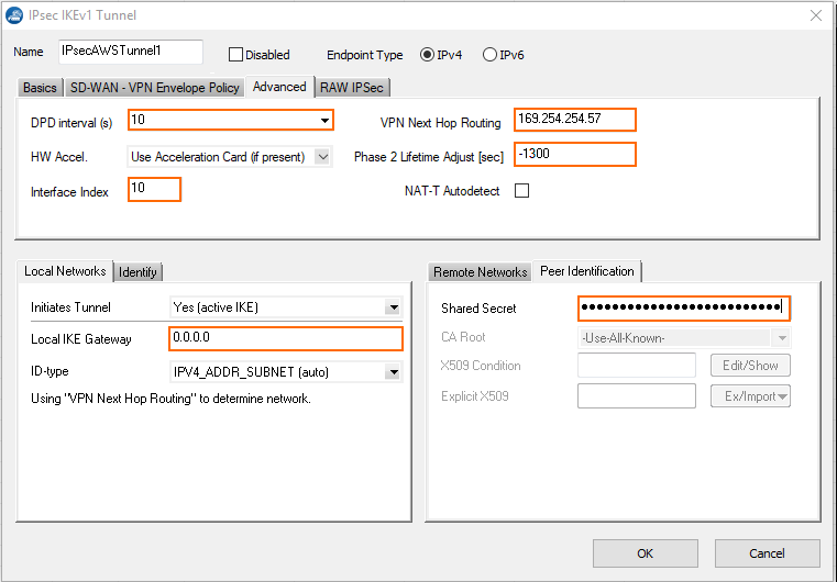
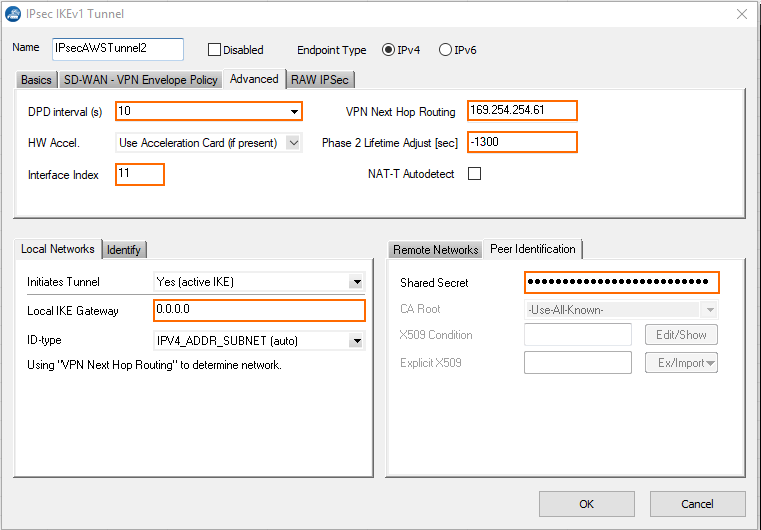
IPsecAWSTunnel1and for IPsec Tunnel 2:IPsecAWSTunnel2 Enter the Phase 1 and Phase 2 settings. The following values are supported for a tunnel to the AWS VPN gateway:
Phase 1 Phase 2 Encryption AES
AES 256AES
AES 256Hash Meth. SHA
SHA256SHA
SHA256DH-Group Group 2
Group 14
Group 15
Group 16
Group 17
Group 18Group 2
Group 5
Group 14
Group 15
Group 16
Group 17
Group 18Lifetime(sec) 28800 3600 Perfect Forward Secrecy - Enable - In the Local Networks tab:
- Local IKE Gateway – Enter your external IP address. If you are using a dynamic WAN interface, or if the appliance is hosted in Azure, AWS or GCP, enter
0.0.0.0 - Network Address – Enter the Inside IP Address of the Customer Gateway (without the /30) and click Add. E.g., IPsec tunnel 1
169.254.254.58and for IPsec tunnel 2169.254.254.62.
- Local IKE Gateway – Enter your external IP address. If you are using a dynamic WAN interface, or if the appliance is hosted in Azure, AWS or GCP, enter
- In the Remote Networks tab:
- Remote IKE Gateway – Enter the Outside IP Address of the Virtual Private Gateway.
- In the Peer Identification tab:
- Shared Secret – Enter the Amazon Pre-Shared Key.
- In the Advanced tab:
- DPD intervals (s) – Enter
10. - Interface Index – Enter the VPN Next Hop Interface index number you entered in step 1.1. E.g., IPsec tunnel 1
10and for IPsec tunnel 211. - VPN Next Hop Routing – Enter the Inside IP address of the Virtual Private Gateway. E.g., IPsec tunnel 1
169.254.254.57and for IPsec tunnel 2169.254.254.61 - (Optional) Phase 2 Lifetime Adjust (sec) – Enter
-1300. This setting ensures that the firewall initiates rekeying.
On CloudGen Firewall devices with firmware 8.0.1 or higher, you can leave this field blank.
- DPD intervals (s) – Enter
- Click OK.
- Enter a Name. E.g, IPsec Tunnel 1:
- Enter the IPsec tunnel configurations:
- Click Send Changes and Activate.
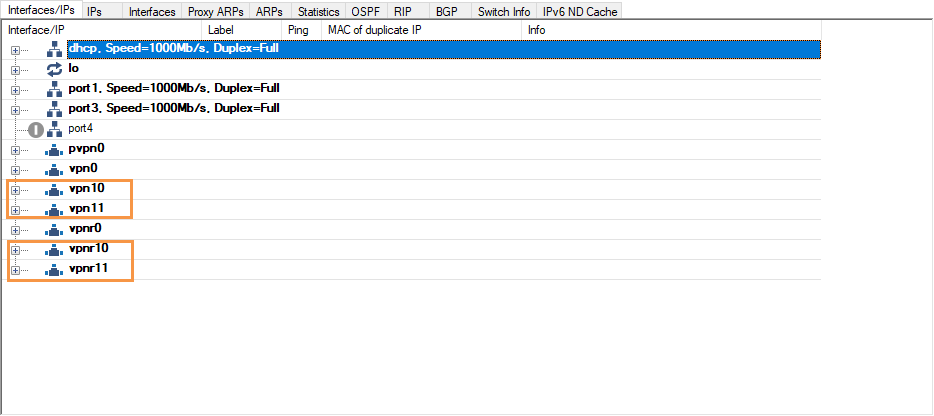
You now have two VPN next-hop interfaces listed in the Interfaces/IPs section on the CONTROL > Network page and the VPN tunnels on the VPN > STATUS page.


Step 3. Configure the BGP Service
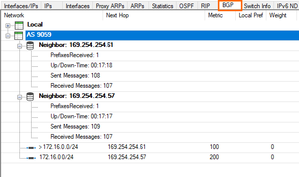
Configure BGP routing to learn the subnets on the other side of the VPN tunnels. The BGP route propagated by the second (backup) IPsec tunnel is artificially elongated so traffic is routed per default over the first IP tunnel, as suggested by Amazon.
Step 3.1. Configure Routes to be Advertised via BGP
Only routes with the parameter Advertise set to yes will be propagated via BGP.
- Go to CONFIGURATION > Configuration Tree > Box > Network.
- Click Lock.
- (optional) To propagate the management network, set Advertise Route to yes.
- In the left menu, click Advanced Routing.
- Double-click on the Routes you want to propagate, and set Advertise Route to yes.
- Click OK.
- Click Send Changes and Activate.
Step 3.2 - Configure the BGP Routes
Configure the BGP setting for the BGP service on the firewall.
- Go to CONFIGURATION > Configuration Tree > Box > Assigned Services > OSPF-RIP-BGP-Service > OSPF/RIP/BGP Settings.
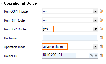
- Select yes from the Run BGP Router list.
- Select advertise-learn from the Operations Mode list.
- In the left menu, click BGP Router Setup.
- Enter your AS Number (e.g.,
64555). - In the Networks table, add the local network(s)(e.g.,
10.10.200.0/24).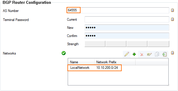
- In the left menu, expand Configuration Mode and click Switch to Advanced Mode.
- Click the Set button for the Advanced Settings. The Advanced Settings window opens.
- Set the Hold timer to
30seconds. - Set the Keep Alive Timer to
10seconds. - Click OK.
- Click Send Changes and Activate.
Step 3.3 - Add a BGP Neighbor for Each IPsec Tunnel
To dynamically learn the routing of the neighboring network, set up a BGP neighbor for each VPN next-hop interface.
- In the left menu of the OSPF/RIP/BGP Settings page, click Neighbor Setup IPv4.
- Click Lock.
- For each IPsec tunnel, click the plus sign (+) next to the Neighbors table to add a new neighbor.
- Enter a Name for the neighbor. E.g.,
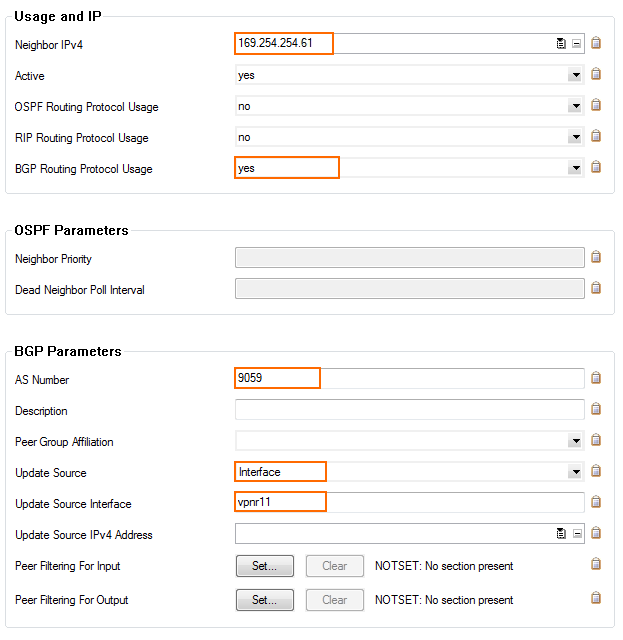
AWS1andAWS2 - In the Neighbors window, configure the following settings in the Usage and IP section:
- Neighbor IPv4 – Enter the inside IP Address of the Virtual Private Gateway (remote address for the VPN next hop interface on the CloudGen Firewall) E.g., IPsec Tunnel 1:
169.254.254.57and for IPsec Tunnel 2169.254.254.61. - OSPF Routing Protocol Usage – Select no.
- RIP Routing Protocol Usage – Select no.
- BGP Routing Protocol Usage – Select yes.
- Neighbor IPv4 – Enter the inside IP Address of the Virtual Private Gateway (remote address for the VPN next hop interface on the CloudGen Firewall) E.g., IPsec Tunnel 1:
- In the BGP Parameters section, configure the following settings:
- AS Number: Enter the ASN for the remote network:
9059 - Update Source: Select Interface
- Update Source Interface: Enter the vpnr interface for the IPsec tunnels. E.g., IPsec Tunnel 1:
vpnr10and for IPsec Tunnel 2vpnr11.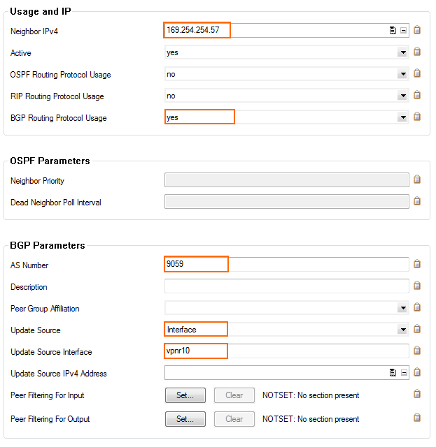
- AS Number: Enter the ASN for the remote network:
- Click OK.
- Click Send Changes and Activate.
Step 3.4 - Add an Access List for the Second IPsec Tunnel
- In the left menu of the OSPF/RIP/BGP Settings page, click Filter Setup IPv4.
- In the Access List IPv4 Filters section, click +.
Enter a Name for the Access List. E.g.,
2ndGWIPThe Access List IPv4 windows opens.Click + to add an access list Type. The Type window opens.
- Select permit from the Type drop-down menu.
- Enter the Inside IP for the Virtual Private Gateway for IPsec Tunnel #2. E.g.,
169.254.254.62to the Network Prefix field. - Click OK.
- Click OK.
Step 3.5 - Add a Filter Setup for the Second IPsec Tunnel
To make the route over the first IPsec tunnel the preferred route, we will lengthen the AS-Path of the second tunnel.
- In the left menu of the OSPF/RIP/BGP Settings page, click Filter Setup IPv4.
Click Lock.
- In the Route Map IPv4 Filters section, click +. The Route Maps IPv4 window opens.
- In the BGP Specific Conditions section, click +. The Route Map Entry window opens.
- In the Route Map Entry window, specify the following settings:
- Sequence Number – Enter a unique sequence number (e.g.,
1). This sequence number must be unique across all route maps. For additional entries, iterate the sequence numbers. - Type – Select permit.
- Match Condition – Select Gateway_IP.
- Gateway IP (Access List) – Select the access list entry created in Step 3.4.
- Set Action – Select AS_Path.
- Set addition to AS-Path – Enter Amazons ASN number
9059.
- Sequence Number – Enter a unique sequence number (e.g.,
- Click OK.
- Click OK.
- Click Send Changes and Activate.
Step 3.6 - Bind the Filters to the Neighbors
- In the left menu of the OSPF/RIP/BGP Settings page, click Neighbor Setup IPv4.
- Click Lock.
- Edit the entries in the Neighbors table.
- In the Neighbors window, click Set/Edit next to Peer Filtering for Input.
- Select the ACL Filter and the Route Map Filter you previously created.
- Click OK.
- Click Send Changes and Activate.
Step 4. Create an Access Rule for VPN Traffic
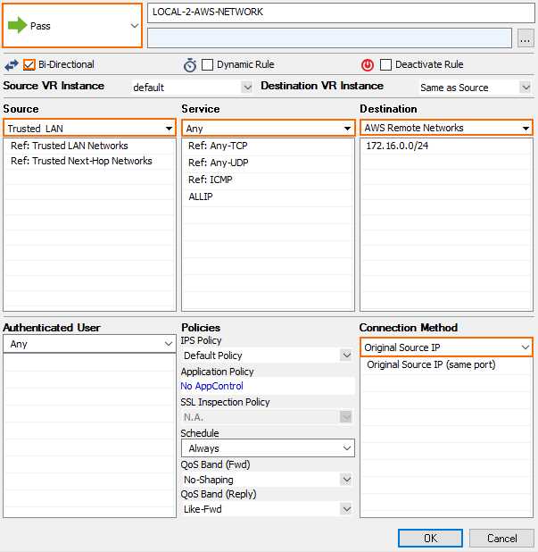
To allow traffic to and from the VPN networks, a pass access rule is needed. You also need to set the Clear DF bit and Force Maximum Segment Size settings according to the Amazon configuration file in the advanced firewall rule settings. You also need to set Reverse Interface (Bi-directional) to Any to allow return traffic using a different VPN tunnel than was used to initiate the connection.
- Create a Pass access rule:
- Bi-Directional – Enable.
- Source – Select the local network(s) you are propagating via BGP.
- Service – Select the service you want to have access to the remote network or ALL for complete access.
- Destination – Select the remote VPC subnet(s).
- Connection Method – Select Original Source IP.
- In the left navigation, click Advanced.
- In the TCP Policy section, set Force MSS (Maximum Segment Size) to
1359.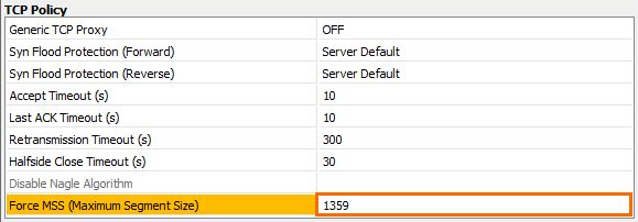
- In the Miscellaneous section, set Clear DF Bit to Yes.

- In the Dynamic Interface Handling section:
- Set Continue on Source Interface Mismatch to Yes.
Set Reverse Interface (Bi-directional) to Any.
Set Interface Checks after Session Creation to Disabled.

- Click OK.
- Move the access rule up in the rule list, so that it is the first rule to match the firewall traffic.
- Click Send Changes and Activate.
You now have two IPsec VPN tunnels connecting your CloudGen Firewalls to the Amazon AWS cloud. Per default, the first IPsec tunnel is chosen. It may take some time for BGP to learn the new routes, in case of a failure.
IPsec Tunnels are Connected (VPN > Status)

BGP Configuration (CONTROL > NETWORK > BGP)
AWS VPN Status in the Amazon AWS Management Interface
- Go to the Amazon VPC Management Console.
- In the left menu, click Site-to-Site VPN Connections.
- Search for your connection created in Step 1.
- Click Tunnel Details.

