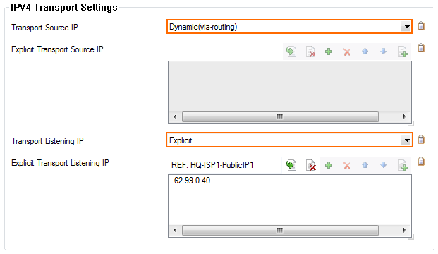
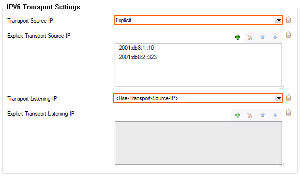
Before adding VPN services to the VPN group, you must configure GTI VPN settings for each service. This information is then used by the GTI Editor when creating VPN tunnels.
- Transport Source IP – The IPv4 or IPv6 address the VPN service is listening on.
- Transport Listening IP – The external IPv4 or IPv6 addresses the VPN service can be reached at.
Before You Begin
Ensure you have switched to the Advanced Configuration mode in Firewall Admin. This will provide access to the necessary configuration options.
Step 1. Add the On-Premises Networks
The Barracuda CloudGen Firewall offers three ways to declare on-premises networks you want to make available through the VPN tunnel as GTI networks:
Add the GTI Networks as Shared Networks
- Go to CONFIGURATION > Configuration Tree > Box > Network.
- In the left menu, select IP Configuration.
- Click Lock.
- In the Shared Networks and IPs section, click +. The Shared Network and IPs window opens.
- Select an Interface for the VPN service.
- In the Network Address field, enter the local IPv4 networks you want to be available over the VPN. E.g.,
10.0.10.0/25 - Select the GTI Network check box.
- Click OK.
- Click Send Changes and Activate.
The local IPv4 network is now displayed in the GTI Networks list.
Select the GTI Networks in the Routing Configuration
- Go to CONFIGURATION > Configuration Tree > Box > Network.
- In the left menu, select Advanced Routing.
- Click Lock.
- In the IPv4 Route Configuration section, edit a configured direct-attached route or create a new one. The IPv4 Routing Table window opens.
- Select the GTI Network check box.
- Click OK.
- Click Send Changes and Activate.
The local IPv4 network is now displayed in the GTI Networks list in Box > Network > IP Configuration.
Add On-Premises Networks to the GTI Netwoks List
- Go to CONFIGURATION > Configuration Tree > Box > Network.
- In the left menu, select IP Configuration.
- Click Lock.
- In the GTI Networks list, click + and add the local IPv4 networks you want to be available over the VPN.
- Click OK.
- Click Send Changes and Activate.
Step 2. Configure the VPN GTI Settings
Configure the IP addresses the VPN service is listening on and the IP addresses through which the VPN service can be reached from the outside. Enter all configured IP addresses. You can remove them later when configuring the VPN tunnel in the GTI Editor as needed.
- Go to CONFIGURATION > Configuration Tree > Multi-Range > your range > your cluster > your box > Assigned Services > VPN Service > VPN GTI Settings.
- Click Lock.
- Configure the IPv4 Transport Settings:
- Select the Transport Source IP:
- All Service IPs – Use all IP addresses defined in the Service Properties of the VPN service.
- First-IP – Use the first IP address of the virtual server. Service properties of the VPN service must be configured to use the first IP address.
- Second-IP – Use the second IP address of the virtual server. Service properties of the VPN service must be configured to use the second IP address.
- Dynamic (via routing) – Source IP address is chosen via routing lookup.
- Explicit – Select Explicit and enter the IP addresses in the Explicit Transport Source IP table.
- Select the Transport Listening IP:
- Use Transport Source IP
- First-IP – Use the first IP address of the virtual server. Service properties of the VPN service must be configured to use the first IP address.
- Second-IP – Use the second IP address of the virtual server. Service properties of the VPN service must be configured to use the second IP address.
- Dynamic (via routing) – Source IP address is chosen via routing lookup.
Explicit – Select Explicit and enter the IP addresses in the Explicit Transport Listening IP table.

- Select the Transport Source IP:
- Configure the IPv6 Transport Settings:
- Select the Transport Source IP:
- All Service IPs – Use all IPv6 addresses defined in the Service Properties of the VPN service.
- Dynamic (via routing) – Source IP address is chosen via routing lookup.
- Explicit – Select Explicit and enter the IPv6 addresses in the Explicit Transport Source IP table.
- Select the Transport Listening IP:
- Use Transport Source IP
Explicit – Select Explicit and enter the IP addresses in the Explicit Transport Listening IP table.

- Click Send Changes and Activate.
Next Step
Add the VPN service to a VPN group and create VPN tunnels using the GTI Editor. For more information, see How to Create a VPN Tunnel with the VPN GTI Editor.
