Teridion Connect provides numerous PoPs (Points of Presence) across the globe, including China, to allow access to their network backbone. The Barracuda CloudGen Firewall can connect to the TCR (Teridion Cloud Router) deployed in one of the PoPs by using IPSec or GRE tunneling to leverage their backbone to improve the connectivity. In addition, BGP can be used as a dynamic routing protocol to learn and propagate networks. For more information, visit the Teridion website.
Connect a Barracuda CloudGen Firewall to the Teridion Network via IPSec
Before You Begin
- Deploy and set up your Teridion infrastructure. For assistance on the Teridion setup, please contact Teridion.
Step 1. Collect Site Information
Log into your Teridion portal and collect the following information:
- From the Site Configuration, collect the information on the PoE IP from the site you need to connect to.

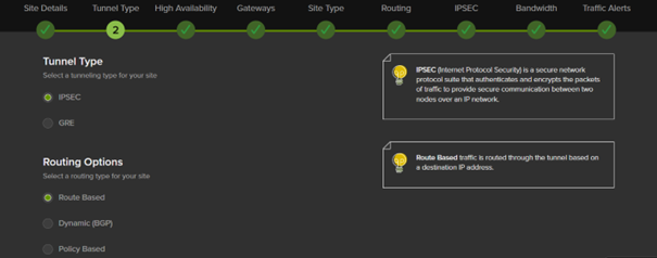
- Tunnel Type
- High Availability (optional)
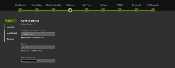
- Gateways IPs
- Transfer Network

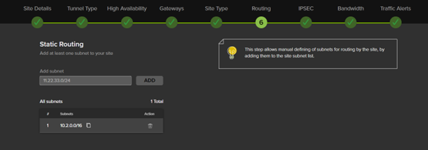
- Static Routing
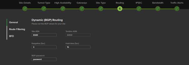
- Dynamic Routing with BGP (optional)
- IPSec IKEv2 Settings
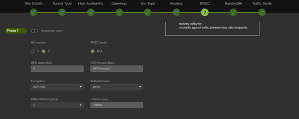
In this example, we have collected the following settings:
- PoE (IP Teridion Router): 52.252.228.31
- SiteID (Firewall Internal IP): 10.2.0.4
- Gateway #1 IP (Firewall Public IP): 23.99.253.105
- Transfer Network TCR IP: 169.254.0.1/30
- Transfer Network Gateway IP: 169.254.0.2/30
IKEv2 Authentication Settings
| Phase 1 | Phase 2 | ||
|---|---|---|---|
Encryption | AES128 | Encryption | AES256 |
Hash | MD5 | Hash | MD5 |
DH-Group | Group 5 | DH-Group | Group5 |
Proposal Handling | Strict | Proposal Handling | Strict |
Lifetime [s] | 28800 | Lifetime | 3600 |
BGP (Optional)
- Teridion ASN: 64500
- Site ASN: 64512
Step 2. Configure IPSec IKEv2 Static Routing
On the Barracuda CloudGen Firewall, do the following:
- Go to Configuration > Configuration Tree > Box > Assigned Services > VPN Service > Site to Site.
- Click on the IPSec IKEv2 tunnel tab.
- Click Lock.
- Right-click the table and select New IKEv2 tunnel. The IKEv2 Tunnel window opens.
- In the IKEv2 Tunnel Name field, enter your tunnel name.
- Set Initiates Tunnel to Yes.

Step 3. Configure Authentication and Encryption
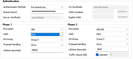
Step 3.1 Configure the Phase 1 encryption settings matching your Teridion setup
- Encryption – Select AES.
- Hash Meth. – Select MD5.
- DH Group – Select Group 5.
- Proposal Handling – Select Strict.
- Lifetime – Enter
28800.
Step 3.2 Configure the Phase 2 encryption settings
- Encryption – Select AES-256.
- Hash Meth. – Select MD5.
- DH Group – Select Group 5.
- Proposal Handling – Select Strict.
- Lifetime (seconds) – Enter
3600. - LIfetime (KB) – Enter
0.
Step 4. Configure Network Settings
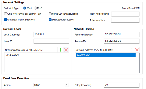
In the Network Settings, set the following values:
- Universal Traffic selector – Select the check box
- IKE Reauthentication - Select the check box
- Local Gateway – Enter your internal IP, e.g.,
10.2.0.4 - Remote Gateway – Enter your PoE IP for TCR, e.g.,
52.252.228.31 - Remote ID – Enter your PoE IP for TCR, e.g.,
52.252.228.31 - Add your Local Network.
- Add your Remote Networks that are reachable via Teridion.
- Set up DPD to match your Teridion configuration.
Step 5. Configure IPsec IKEv2 Dynamic Routing
Create a VPN next hop interface:
- Go to CONFIGURATION > Configuration Tree > Box > Assigned Services > VPN-Service > VPN Settings.
- Click Lock.
- In the left menu, click Routed VPN.
- Click Add in the VPN Next Hop Interface Configuration section.
- Configure the following settings:
- VPN Interface Index – Enter a number between 0 and 99. Each interface index number must be unique.
- MTU – Enter
1398 - IP Addresses – Enter Transfer Network GW IP, e.g.,
169.254.0.2/30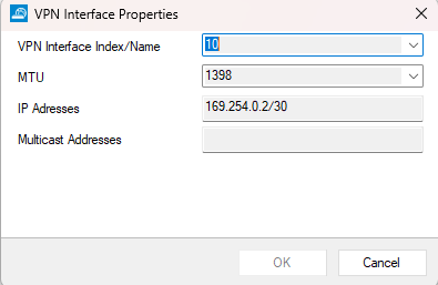
- Click OK.
Step 5.1 Add the VPN next hop interface IP address to the shared IPs
- Go to CONFIGURATION > Configuration Tree > Box > Network.
- Click Lock.
- In the left menu, click IP Configuration.
- In the Shared Networks and IPs section, click +.
- Enter a name for the shared IP address, and click OK.
- The Shared Networks and IPs window opens. Configure the following settings:
- Interface – Select other and enter
vpnr10. - Network Address – Enter the network address of the Transfer Network in CIDR format:
169.254.0.0/30. - Click Shared IPs in this Network. The Shared IPs in this Network window opens. Enter the following:
- IP Address – Enter the IP address for the VPN interface of the CloudGen Firewall, e.g.,
169.25.0.2 - Alias for this IP – Select None.
- Respond to Ping – Select yes.
- IP Address – Enter the IP address for the VPN interface of the CloudGen Firewall, e.g.,
- Click OK.
- Trust Level – Select Unclassified.
- Active – Select Yes.
- Interface – Select other and enter
- Click OK.
- Click Send Changes and Activate.
Step 6. Configure the Site-to-Site IPSec IKEv2 VPN Service
- Go to Configuration > Configuration Tree > Box > Assigned Services > VPN Service > Site to Site.
- Click on the IPSec IKEv2 tunnel tab.
- Click Lock.
- Right-click the table and select New IKEv2 tunnel. The IKEv2 Tunnel window opens.
- In the IKEv2 Tunnel Name field, enter your tunnel name.
- Set Initiates Tunnel to Yes.

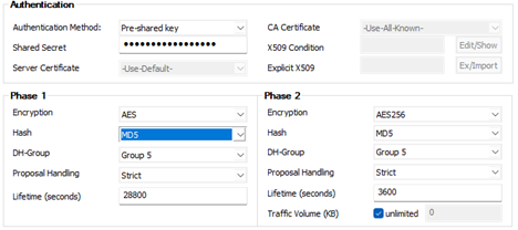
Step 6.1 Configure the Phase 1 encryption settings matching your Teridion setup
- Encryption – Select AES.
- Hash Meth. – Select MD5.
- DH Group – Select Group 5.
- Proposal Handling – Select Strict.
- Lifetime – Enter
28800.
Step 6.2 Configure the Phase 2 encryption settings
- Encryption – Select AES.
- Hash Meth. – Select MD5.
- DH Group – Select Group 5.
- Proposal Handling – Select Strict.
- LIfetime (KB) – Enter
0.
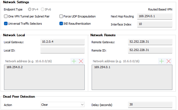
In the Network Settings, set the following values:
- Universal Traffic selector – Select the check box
- IKE Reauthentication - Select the check box
- Next Hop Routing – Enter the TCR IP collected in the beginning:
169.254.0.1 - Interface Index – Enter the interface index created in Step 1.
- Local Gateway – Enter your internal IP, e.g.,
10.2.0.4 - Remote Gateway – Enter your PoE IP for TCR, e.g.,
52.252.228.31 - Remote ID – Enter your PoE IP for TCR, e.g.,
52.252.228.31 - Set up DPD to match your Teridion configuration.
9. Click OK.
10. Click Send Changes and Activate.
Step 7. Configure the BGP Service
Configure BGP routing to learn the subnets from the remote BGP peer behind the Teridion network.
- Go to CONFIGURATION > Configuration Tree > Box > Network.
- Click Lock.
- (optional) To propagate the management network, set Advertise Route to yes.
- In the left menu, click Advanced Routing.
- Double-click the Routes you want to propagate, and set Advertise Route to yes.
- Click OK.
- Click Send Changes and Activate.
Step 7.1 Enable BGP
Configure the BGP setting for the BGP service on the firewall.
- Go to CONFIGURATION > Configuration Tree > Box > Assigned Services > OSPF-RIP-BGP-Service > OSPF/RIP/BGP Settings.
- In the left menu, click BGP Router Setup.
- Enter the AS Number for your network, e.g.,
64500 - In the Terminal Password fields, specify a password for connecting to the BGP router service via telnet from the shell of the Barracuda CloudGen Firewall.
- Click OK.
- Click Send Changes and Activate.
Step 7.2 Configure the BGP Neighbor
- Go to CONFIGURATION > Configuration Tree > Box > Assigned Services > Dynamic Routing (OSPF-RIP-BGP-Service) > OSPF/RIP/BGP Settings.
- In the left menu of the OSPF/RIP/BGP Settings page, click Neighbor Setup IPv4.
- Click Lock.
- In the left menu, expand Configuration Mode and click Switch to Advanced Mode.
- Click + to add an entry to the Neighbors table. The Neighbors window opens.
- Enter a Name and click OK.
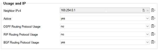
- In the Neighbors window, configure the following settings in the Usage and IP section:
- Neighbor IPv4 – Enter the remote BGP peer IP address, e.g.,
169.254.0.1 - OSPF Routing Protocol Usage – Select no.
- RIP Routing Protocol Usage – Select no.
- BGP Routing Protocol Usage – Select yes.
- Neighbor IPv4 – Enter the remote BGP peer IP address, e.g.,
- In the BGP Parameters section, configure the following settings:
- AS Number – Enter the ASN for the remote network as collected in the preparation.
- Update Source – Select Interface.
- Update Source Interface – Enter the vpnr interface. E.g.,
vpnr10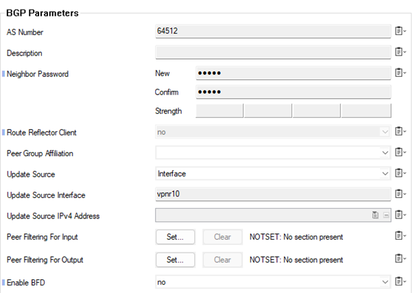
- Click OK.
- Click Send Changes and Activate.
