Before Getting Started
- Verify that you have the cage nuts and screws to attach the appliance to your rack; these are not provided by Barracuda;
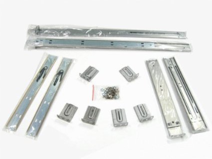
- Verify that you have the rail kit included with your appliance, including the hardware to assemble the rails;
- Verify the rack unit is set up in a Restricted Access Location, for example, dedicated equipment rooms, service closets, and other secure, clean, dust-free well ventilated environments;
Allow enough clearance in front of the rack to allow the front door to open completely (~25 inches);
- Verify approximately 30 inches of clearance is available in the back of the rack to allow for sufficient airflow and ease of servicing;
- Verify the area does not generate heat, electrical noise, or electromagnetic fields;
- A grounded power outlet is available.
Inspect the Packaging
Before getting started, inspect the shipping box and note if there is any damage. If the chassis itself shows any damage, file a damage claim with the carrier who delivered your Barracuda Networks appliance.
Install the Appliance in the Rack
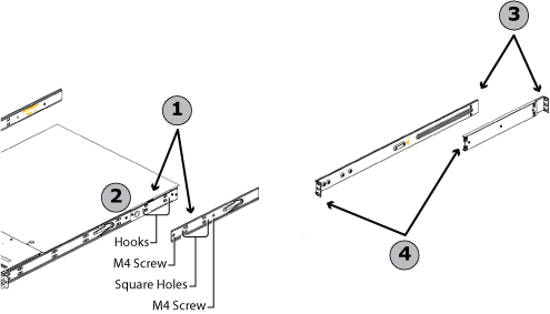
Install Inner and Outer Slides
Use the following steps to install the inner slides, as shown in Figure 1.
- Locate the right inner slide, the slide that will be attached to the right side of the chassis when facing the front panel of the chassis, and align the four square holes on the right inner slide against the hook on the right side of the chassis slide the long bracket into the short bracket (1).
- Securely attach the slide to the chassis with two M4 flat head screws (2).
- Repeat steps 1 and 2 to install the left inner slide to the left side of the chassis.
- Measure the distance from the front rack rail to the rear rail of the rack.
- Attach a short bracket to the rear side of the right outer slide, and a long bracket to the front side of the right outer slide (3).
- Adjust the short and long brackets to the proper distance so that the chassis will fit snugly into the rack (4).
- Secure the slides to the rack with the provided screws.
- Repeat steps 4 through 7 for the left outer slide.
Figure 1. Install Inner and Outer Rack Rail Sections.
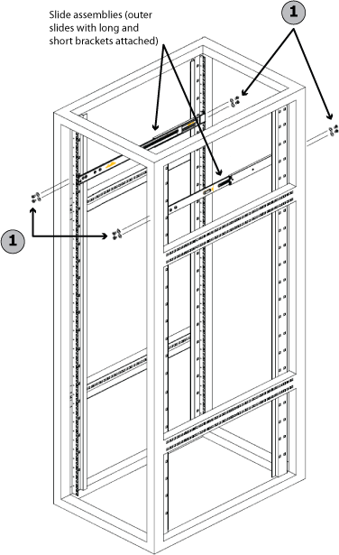
Install Slide Assemblies
Secure the slide assemblies to the rack using four M5 screws and washers (1), as shown in Figure 2:
Figure 2. Install Slide Assemblies.
Install Chassis into the Rack
Use the following steps to install the chassis into the rack.
- Push the inner slides, which are attached to the chassis, into the grooves of the outer slide assemblies (1), as shown in Figure 3.
Figure 3. Install the Chassis into the Rack.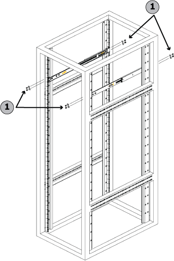
- Push the chassis into the outer slide assemblies (2), as shown in Figure 4:
Figure 4. Insert Chassis into Rack.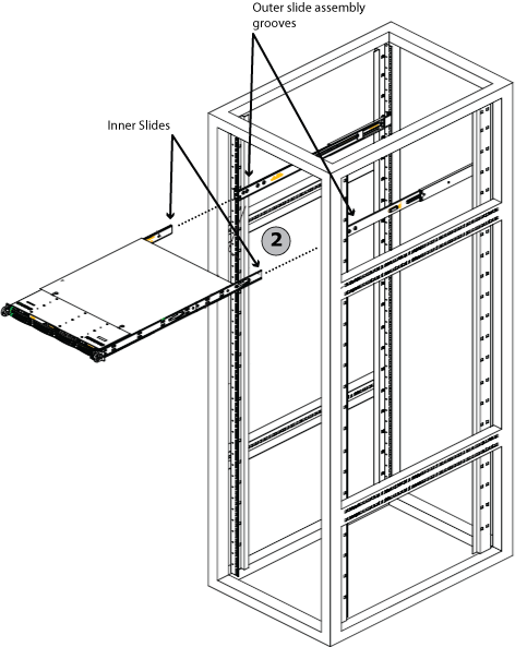
- Push the chassis all the way to the back of the outer slide assemblies (3), as shown in Figure 5:
Figure 5. Push the Chassis to the Back of the Outer Slide Assemblies.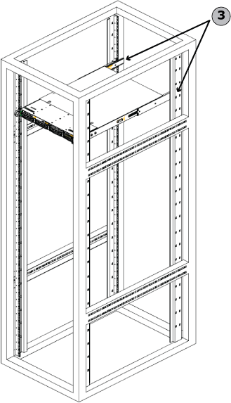
For detailed configuration steps, refer to the Getting Started section for the rack mounted appliance.
Remove the chassis from the rack
In Figure 6 below, the locking clips on the rails are circled. In Figure 7, see the locking clips on the two far left rails. These clips must be released when removing the server.
Figure 6. Locking clips.
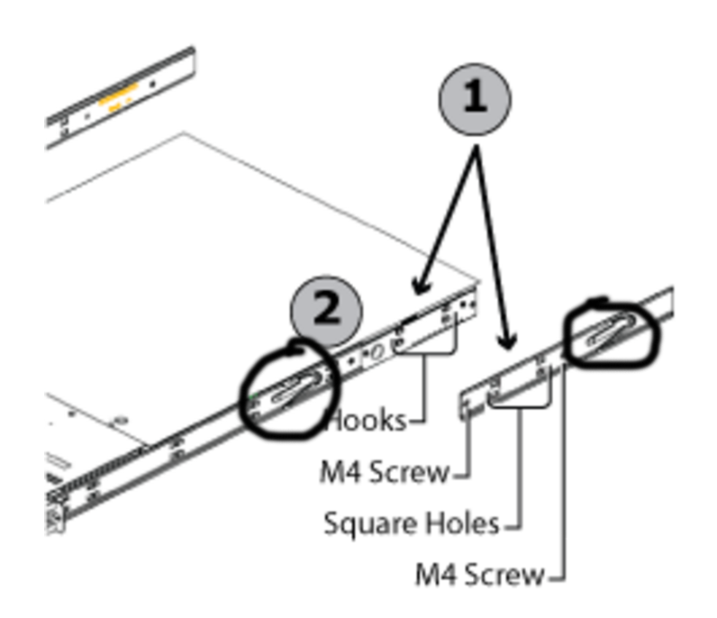
Figure 7. Black locking clips shown on rails on left of photo.