Connecting multiple VPCs to multiple locations, such as your datacenter or customer offices, can cause significant configuration overhead, especially if VPCs are frequently added and removed. For example, adding a new VPC requires configuration changes to each on-premises location. A second weak point is the communication between the VPCs. To share common resources, VPCs must be peered if they are in the same region; otherwise, the traffic must be routed through your datacenter.
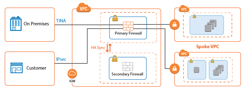
To reduce the number of VPN connections required by each device participating in the network, use a central VPC as a Transit VPC and arrange the VPCs in a hub and spoke topology. The Transit VPC uses a CloudGen Firewall High Availabilty Cluster or a CloudGen Firewall Cold Standby Cluster as the VPN hub for all site-to-site VPN tunnels.
Shared services used by all spoke VPCs can be located in the Transit VPC or in a separate VPC peered to the Transit VPC. The service VPC can also host replicated on-premises services to save bandwidth to the datacenter.
Use Cases for a CloudGen Firewall Transit VPC
The Transit VPC is a very versatile and flexible architecture that can be combined with the other reference architectures, except multi-NIC Segmentation, to create a central firewall hub for all your cloud resources.
Deploying a Transit VPC via CloudFormation Templates
It is recommended to deploy the Transit VPC via a CloudFormation template. The template deploys a CloudGen High Availability Cluster in the Transit VPC and two spoke VPCs with VPN gateways. The firewalls are automatically joined into the High Availability Cluster, but failing over the Elastic IP addresses requires manual configuration steps.
To configure the site-to-site VPN from the VPN gateways:
- Create an IAM role for the firewall cluster. For step-by-step instructions, see How to Create an IAM Role for a CloudGen Firewall in AWS.
- Download the CGF_HA_floatingEIP.json template and parameter file from the Barracuda Network GitHub account: https://github.com/barracudanetworks/ngf-aws-templates/tree/master/HA%20Cluster.
- Accept the Software Terms for the Barracuda CloudGen Firewall PAYG or BYOL image in the AWS Marketplace.
- Create a parameter template file containing your parameters values.
Deploy the CGF_HA_floatingEIP.json CloudFormation template via AWS CLI or AWS console.
aws cloudformation create-stack --stack-name "YOUR_STACK_NAME"--template-body YOUR_S3_BUCKET/CGF_HA_floatingEIP.json --parameter YOUR_S3_BUCKET/NGF_TransitVPC_parameters.json
During deployment, the following resources are created by the template:
- One Transit VPC with a CloudGen Firewall High Availability Cluster.
- Two Elastic IP addresses for the firewall cluster.
- Two spoke VPCs with VPN gateways.
After deploying the template, the following manual configuration steps are required to finish the setup:
- Configure site-to-site VPN tunnels and BGP routing for each VPN gateway.
- Configure Elastic IP addresses to fail over with the firewall services.
For step-by-step instructions on how to deploy a CloudFormation template, see How to Deploy a CloudGen in AWS via CloudFormation Template.
Configure Elastic IP Address Transfer
Since the AWS VPN gateway can only be configured to use one IP address, the same elastic IP address must always be associated with the active firewall in the cluster. Configure the firewall to execute an AWS CLI command that reassigns the Elastic IP addresses every time the firewall fails over. Write down the Elastic IP addresses associated with the primary and secondary firewalls:
- Primary Firewall – Elastic IP address for the active firewall.
- Secondary Firewall – Elastic IP address for the passive firewall.
- Log into the primary firewall with Barracuda Firewall Admin.
- Go to CONFIGURATION > Configuration Tree > Box > Infrastructure Services > Control.
- In the left menu, click Switch to Advanced.
- In the left menu, click Custom Scripts.
- Click Lock.
In the Start Script section, enter the AWS CLI command to re-associate the active Elastic IP address when the firewall starts.
/opt/aws/bin/aws ec2 associate-address --instance-id $(/usr/bin/curl -s http://169.254.169.254/latest/meta-data/instance-id) --allocation-id ACTIVE_ELASTIC_IP_ID --allow-reassociationIn the Stop Script section, enter the AWS CLI command to re-associate the passive Elastic IP address when the firewall shuts down.
/opt/aws/bin/aws ec2 associate-address --instance-id $(/usr/bin/curl -s http://169.254.169.254/latest/meta-data/instance-id) --allocation-id PASSIVE_ELASTIC_IP_ID --allow-reassociation- Click Send Changes and Activate.
AWS VPN Gateway
The AWS VPN gateway connects the EC2 instances in the VPC to the Transit VPC via VPN connections. The customer gateway is configured for the Elastic IP address associated with the active firewall. Each VPN connection to the AWS VPN gateway is made up of two parallel IPsec IKEv1 tunnels. BGP is configured on the firewall to prefer the first tunnel and to use the secondary tunnel in case the primary is down.
The routing between the Transit VPC and the spokes is handled by BGP. The spoke VPCs learn the default route from the firewall and send all traffic through the VPN gateway and the Transit VPC high availability firewall cluster. The firewall learns the spoke VPC networks propagated by the VPN gateway. When a spoke VPC is added or removed, BGP automatically propagates the changes to all connected networks.
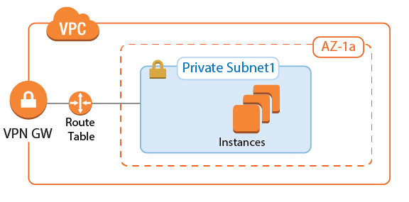
For step-by-step instructions, see Step 1 in How to Configure an IKEv1 IPsec VPN to an AWS VPN Gateway with BGP.
AWS Route Tables
The AWS route tables can be configured with static routes over the VPN gateway, or they can be configured to learn the routes via BGP. Using BGP has the advantage of being able to control all routing in the firewall's BGP service. However, whether static or dynamic, it is recommended to configure the default route through the VPN gateway. This ensures that all traffic for the VPC passes through the firewalls and that the security policies can be applied in one central location.
Configure the AWS route table for the spoke VPCs to learn the routes propagated by the firewall BGP service. To send all traffic through the Transit VPC, propagate the default route to the spoke VPCs. If propagated routes in the AWS route tables overlap with the local route of the VPC, the local route is always preferred. This applies not only to the local route, but also to all static routes. Static routes are preferred over the learned routes.
Enabling Route Propagation for AWS Route Tables
- Log into the AWS console.
- Click Services, and select VPC.
- In the Virtual Private Cloud section of the left menu, click Route Tables.
- (optional) Filter the list using the VPC ID.
- Select the route table for the spoke VPC.
- In the lower half of the page, click the Route Propagation tab.
- Click Edit.
- Select the VPN gateway and click Save.

Configure the IPsec Tunnels on the Transit VPC Firewalls
To connect the spoke VPC to the Transit VPC, configure two IPsec tunnels: two parallel IPsec tunnels to the Elastic IP of the active firewall. AWS defines a /30 intermediary network for each IPsec tunnel. The IP addresses in this intermediary network are used by BGP. Define BGP neighbors for each next-hop address as per the instructions provided by AWS.
The VPN connection information is unique for each VPN connection and can be downloaded by right-clicking the VPN connection. In addition to the encryption settings in the AWS configuration file, the following settings are supported:
- Encryption – AES, AES256
- Hash – SHA1, SHA256
- Phase 1 DH-Group – Group 2 and Group 14-18
- Phase 2 DH-Group – Group 1, 2, 5 and Group 14-18

For step-by-step instructions, see Step 2 in How to Configure an IKEv1 IPsec VPN to an AWS VPN Gateway with BGP.
Configure BGP on the Transit VPC Firewalls
The BGP service on the firewall learns and propagates the routes from each location. Create a BGP neighbor configuration for each IPsec tunnel and each on-premises network connected to the Transit VPC. If you are not using a static route in the spoke VPCs routing table, propagate the default route to the BGP neighbor for each spoke VPC. The VPN gateway automatically propagates the VPC network via BGP. Since spoke VPCs are always connected by two parallel IPsec tunnels, the route over one IPsec tunnel should be preferred over the other.
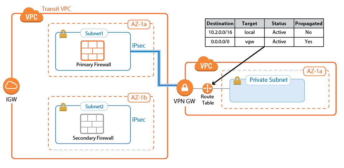
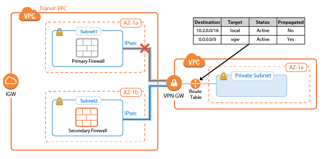
Configure the BGP service on each firewall to exchange information with the BGP service on the other side of the VPN tunnels. Using Route Maps , modify the routes learned for the second of the parallel IPsec connections. By lengthening the AS PATH of the IPsec tunnels, traffic is sent through the first tunnel at all times, unless the tunnel is down.


For step-by-step instructions, see Step 3 in How to Configure an IKEv1 IPsec VPN to an AWS VPN Gateway with BGP .
Create Access Rules to Allow Traffic
By default, the Forwarding Firewall service blocks all traffic not explicitly allowed by an access rule. Since all traffic is routed through the Transit VPC, create access rules to allow access for individual services and/or entire networks. Access rules allowing traffic through the AWS VPN gateway IPsec tunnels must set the following advanced access settings:
- Force MSS (Maximum Segment Size) – Set to
1387. - Clear DF Bit – Set to yes.
- Reverse Interface (Bi-directional) – If you are using two parallel IPsec tunnels per firewall, set this to Any. This allows the traffic to use either IPsec tunnel.
Be sure to sync the access rules on both firewalls to make sure that the behavior is identical no matter which firewall the traffic is sent through.
For step-by-step instructions, see Step 4 in How to Configure an IKEv1 IPsec VPN to an AWS VPN Gateway with BGP .
Launching EC2 Instances in Spokes
If your Transit VPC is created with spokes in a single CloudFormation template, the instances will not have Internet access during launch. Use NAT gateways or VPC endpoints in the spoke VPC to access AWS services before the VPN connection and BGP routing to the firewall is configured.
If your spoke is already connected, verify that access rules are in place that allow the new instance access to all resources required during the provisioning process. If unsure, log into the active firewall and use the Firewall > History page in Barracuda Firewall Admin to check if traffic from the instance was blocked.
For more information , see Barracuda Firewall Admin History Page .
Connecting to On-Premises Networks
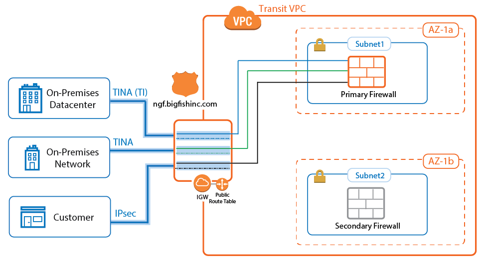
To be able to forward traffic between your AWS VPC and your on-premises networks, create site-to-site VPN tunnels between the High Availability Cluster in the Transit VPC and the VPN gateways in each remote location.
The networks of the spoke VPC are propagated via BGP over the VPN tunnels. BGP is used to propagate the AWS VPC networks to your on-premises locations. Depending on the remote device, you can use either Barracuda Networks' proprietary TINA VPN or the industry standard IPsec VPN protocol. Failover and preference of the VPN tunnel to the primary firewall is handled by BG P.
TINA Site-to-Site VPN Tunnels to CloudGen Firewalls
If the remote location uses a CloudGen Firewall, you can take advantage of the TINA VPN protocol. TINA offers many enhancements not featured in the standard IPsec protocol, such as SD-WAN and Traffic Compression. SD-WAN is a logical layer used to manage multiple parallel VPN tunnels (transports) in one VPN tunnel configuration. So if your remote location has multiple Internet connections (perhaps in combination with AWS Direct Connect), all connections can be combined into one VPN tunnel. SD-WAN patterns in the connection object of the access rule determine how the traffic is distributed over the VPN transports and failover behavior. Compression reduces the amount of traffic sent through the tunnel by using data deduplication .
For more information, see How to Configure BGP Routing over a TINA VPN Tunnel and SD-WAN.
IPsec Site-to-Site VPN Tunnels to Third-Party Devices
Third-party VPN gateways can be connected via IPsec IKEv1 or IKEv2 VPN tunnels. The remote device must support routing BGP over IPsec tunnels to be able to learn the routes. Create one IPsec tunnel from the active EIP for each on-premises location.
For more information, see How to Configure BGP Routing over an IKEv1 IPsec VPN Tunnel.
Create Access Rules for On-Premises Networks
Just like when connecting the spoke VPCs, the firewall blocks all traffic by default. To allow connections to the networks learned via BGP, create pass access rules on both firewalls. These rules must be the same on both firewalls to ensure that if the connection fails over to the secondary firewall, the same policies are applied. Access rules to cloud services connected to the Transit VPC via VPC peering must translate the source IP address to the IP address of the DHCP interface of the firewall to satisfy the AWS restriction on peering that transitive VPCs are not allowed.
Internet to Backend Services
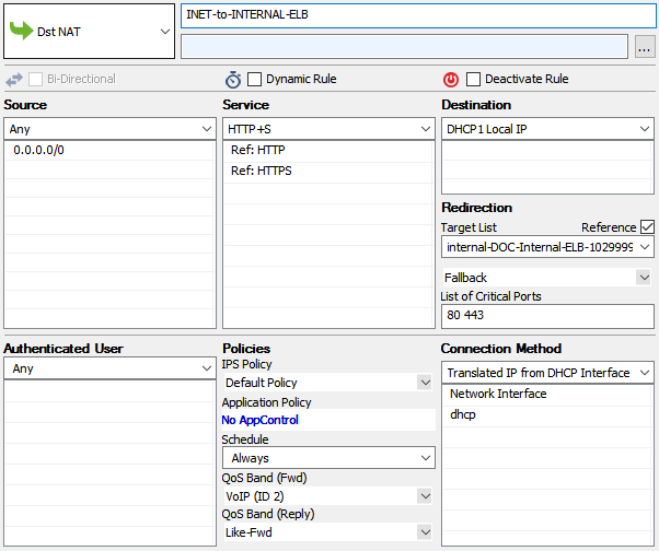
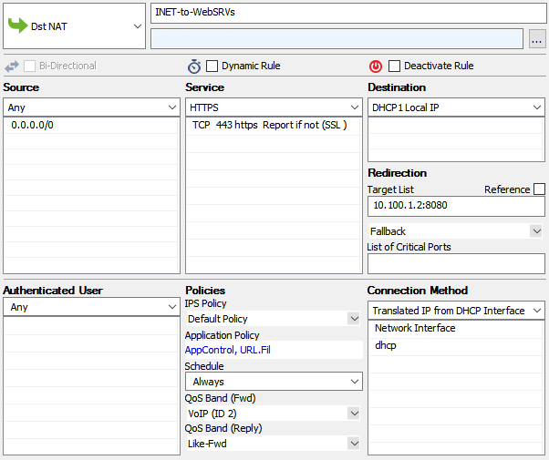
Create the following access rule to forward traffic from the Internet to an internal web server.

- Action – Select Dst NAT.
- Source – Select Any or a network object containing the networks the ELB is deployed in.
- Service – Select the service. E.g., HTTP+S.
- Destination – Select DHCP1 Local IP.
- Connection Method – Select Dynamic NAT or Translated from DHCP Interface.
Redirection Target – Enter the IP address of the backend service. Optionally, append the port number to redirect to a different port. e.g,
10.100.1.2or10.100.1.2:8080
Redirect Traffic through a WAF Cluster or Other Service Behind an Internal ELB
Services behind an internal ELB can also be forwarded via Dst NAT access rule.

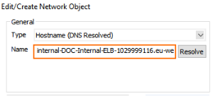
- Create a hostname network object for the internal DNS name of the ELB and click Send Changes.
- Create the access rule:
- Action – Select Dst NAT.
- Source – Select Any or a network object containing the networks the ELB is deployed in.
- Service – Select the service. E.g., HTTP+S.
- Destination – Select DHCP1 Local IP.
- Connection Method – Select Dynamic NAT or Translated from DHCP Interface.
Redirection Target – Click Reference and select the network object for the ELB.
