The Barracuda CloudGen Firewall can establish IPsec VPN tunnels to any standard-compliant IKEv2 IPsec VPN gateway. The site-to-site IPsec VPN tunnel must be configured with identical settings on both the firewall and the third-party IKEv2 IPsec gateway.

Before You Begin
If not already present, configure the Default Server Certificate in CONFIGURATION > Configuration Tree > Box > Assigned Services > VPN-Service > VPN Settings. For more information, see VPN Settings.
Step 1. Configure the VPN Service Listeners
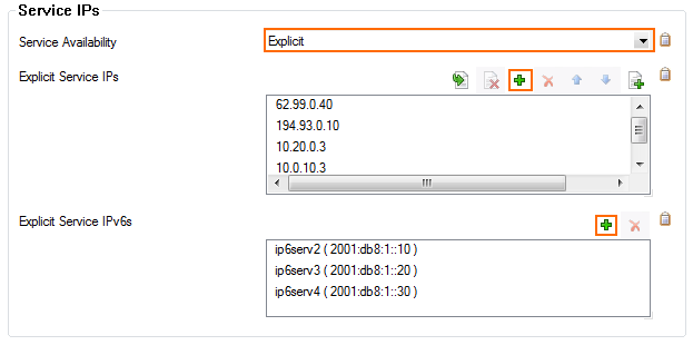
Configure the IPv4 and IPv6 listener addresses for the VPN service.
- Go to CONFIGURATION > Configuration Tree > Box > Assigned Services > VPN-Service > Service Properties.
- Click Lock.
From the Service Availability list, select the source for the IPv4 listeners of the VPN service.
When selecting Explicit, click + for each IP address and enter the IPv4 addresses in the Explicit Service IPs list.
- Click + to add an entry to the Explicit IPv6 Service IPs.
- Select an IPv6 listener from the list of configured explicit IPv6 service IP addresses.

- Click Send Changes and Activate.
Step 2. Create an IKEv2 IPsec Tunnel on the CloudGen Firewall
- Go to CONFIGURATION > Configuration Tree > Box > Assigned Services > VPN-Service > Site to Site.
- Click the IPsec IKEv2 Tunnels tab.
- Click Lock.
- Right-click the table and select New IKEv2 Tunnel. The IKEv2 Tunnel window opens.
- Enter a Tunnel Name.
- Set Initiates Tunnel:
- Yes – The firewall is the active unit and continuously attempts to connect to the remote VPN gateway until a VPN tunnel is established.
No – The firewall is the passive unit and waits for connection attempts from the remote VPN gateway.

- Select the Authentication Method:
Pre-shared key – Enter the Shared Secret to use a shared passphrase to authenticate.
- CA certificate – Select a Server Certificate, CA Root certificate, and enter an X509 Condition to use certificate authentication.
- X509 certificate (explicit) – Select a Server Certificate and import an Explicit X509 certificate.

- Select the Phase 1 settings:
- Encryption – Select the encryption algorithm: AES, 3DES, Blowfish, or AES256.
- Hash – Select the hashing algorithm: MD5, SHA, SHA256, or SHA512.
- DH-Group – Select the Diffie-Hellman Group. Supported groups are: 1, 2, 5, 14 - 21.
- Proposal Handling
- Strict – The effective encryption is strictly determined by the proposed set of Encryption, Hash, and Group. The communication partner must agree with the proposed set; otherwise, no communication will be established due to a missing common encryption agreement.
- Negotiate – This option lets a communication partner decrease the strength of the encryption if it cannot support the proposed encryption from the initiator.
- Lifetime (seconds) – Enter the number of seconds until the IPsec SA is re-keyed. Default:
28800
- Select the Phase 2 settings:
- Encryption – Select the encryption algorithm: AES, 3DES, Blowfish, or AES256.
- Hash – Select the hashing algorithm: MD5, SHA, SHA256, or SHA512.
- DH-Group – Select the Diffie-Hellman Group. Supported groups are: 1, 2, 5, 14 - 21.
- Proposal Handling
- Strict – The effective encryption is strictly determined by the proposed set of Encryption, Hash, and Group. The communication partner must agree with the proposed set; otherwise, no communication will be established due to a missing common encryption agreement.
- Negotiate – This option lets a communication partner decrease the strength of the encryption if it cannot support the proposed encryption from the initiator.
- Lifetime (seconds) – Enter the number of seconds until the IPsec SA is re-keyed. Default:
3600. - Lifetime (KB) – Enter the number of KB after which the IPsec SA is re-keyed.

- Select the IP Version of the local listener and the remote gateway.
- IP Version – Click IPv4 or IPv6 to match the Local Gateway and Remote Gateway IP address IP versions.

- (optional) Select Advanced Network Settings
- One VPN Tunnel per Subnet Pair – Creates a dedicated security association for each subnet pair. This is needed if the remote device is a Cisco ASA or a SonicWall.
- Force UDP Encapsulation – Use UDP encapsulation (4500) for ESP traffic even if no NAT is detected.
- Universal Traffic Selector – Instruct peer to route all traffic into the tunnel. This is needed if the remote device is a Checkpoint firewall.
IKE Reauthentication – Reauthenticate during every IKE rekeying. This setting must be disabled if the remote device is a Microsoft Azure Dynamic VPN Gateway or a SonicWall.
- Next Hop Routing – Sets the next hop IP address for routed VPN traffic.
- Interface Index – The number of the virtual interface to be used for routed VPN.

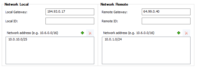
- Enter the Network Local settings:
Local Gateway – Enter the external IP address of the firewall. If you are using a dynamic WAN IP address, enter
0.0.0.0.- Local ID – Enter an IP address, FQDN, email, or a distinguished name. If left blank, the local gateway IP is used.
- Network Address – Add the local networks you want to reach through the VPN tunnel, and click Add.
- Enter the Network Remote settings:
- Remote Gateway – Depending on the setting of Initiate Tunnel, this edit field accepts different inputs:
- Initiate Tunnel = Yes – The input must be a hostname or IP address. No network IPs in CIDR notation are allowed.
- Initiate Tunnel = No – The input must be an IP address or network address. If the remote appliance is using dynamic IP addresses, enter
0.0.0.0/0.
- Remote ID – Enter a unique ID. VPN tunnels without remote ID will not be established successfully.
- Network Address – Add the IP address of the remote network, and click Add.

- Remote Gateway – Depending on the setting of Initiate Tunnel, this edit field accepts different inputs:
- Enter the Dead Peer Detection settings:
- Action:
- None – Disable DPD.
- Clear – Connection with the dead peer is stopped, and routes removed.
- Hold – Connection is put in a hold state.
- Restart – The connection is restarted.
- Delay (seconds) – Enter the number of seconds after which an empty INFORMATIONAL message is sent to check if the remote peer is still available.

- Action:
- Click OK.
- Click Send Changes and Activate.
Step 3. Create an IPsec Tunnel on the Remote Appliance
Configure the remote firewall or third-party VPN gateway with the same settings. Only the local and remote networks and the IP address for the remote VPN gateway must be interchanged.
Step 4. Create Access Rules for VPN Traffic
To allow traffic in and out of the VPN tunnel, create a Pass access rule.
For more information, see How to Create Access Rules for Site-to-Site VPN Access.
Monitoring a VPN Site-to-Site Tunnel
To verify that the VPN tunnel was initiated successfully and traffic is flowing, go to VPN > Site-to-Site or VPN > Status.

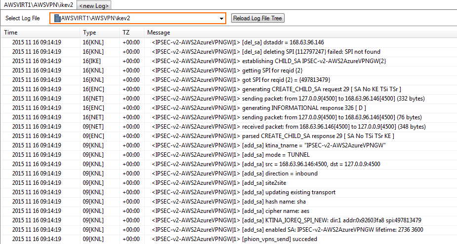
Go to LOGS and select the /<your_vpn_service>/IKEv2 log file.

