Follow the instructions in this article to configure the BGP service with an intermediary /30 network between a local and remote VPN gateway. The BGP service uses the IPsec tunnel to dynamically learn the routes of the remote network. You must configure both the local and remote Barracuda CloudGen Firewalls.

| Example Values for the Local Barracuda CloudGen Firewall | Example Values for the Remote Barracuda CloudGen Firewall | |
|---|---|---|
| VPN Next Hop Interface Index | 13 | 13 |
| VPN Next Hop Interface IP Address | 192.168.22.1/30 | 192.168.22.2/30 |
| Shared Network IP Address | 192.168.22.1 | 192.168.22.2 |
| VPN Local Networks | 192.168.22.0/30 | 192.168.22.0/30 |
| VPN Remote Networks | 192.168.22.0/30 | 192.168.22.0/30 |
| VPN Interface Index | 13 | 13 |
| VPN Next Hop Routing | 192.168.22.2 | 192.168.22.1 |
| ASN | 64577 | 64579 |
| Router ID | 192.168.22.1 | 192.168.22.2 |
| Neighbor IPv4 | 192.168.22.2 | 192.168.22.1 |
| Neighbor AS Number | 64579 | 64577 |
| Neighbor Update Source Interface | vpnr13 | vpnr13 |
Before You Begin
Before you configure BGP over an IPsec VPN, obtain the following:
- A free /30 subnet. E.g.,
192.168.22.0/30 - Autonomous system numbers (ASNs) for the remote and local networks. The ASNs can be private or public because the VPN is not directly connected to the Internet.
Step 1. Add a VPN Next Hop Interface
Add a VPN next hop interface using a /30 subnet.
- Go to CONFIGURATION > Configuration Tree > Box > Assigned Services > VPN-Service > VPN Settings.
- Click Lock.
- In the left menu, select Routed VPN.
- Next to the Next Hop Interface Configuration table, click Add.
- Configure the VPN next hop interface settings:
- In the VPN Interface Index field, enter a number between
0and999. E.g.,13 - In the IP Addresses field, enter the VPN interface IP address. E.g.,
192.168.22.1/30for the local firewall or192.168.22.2/30for the remote firewall.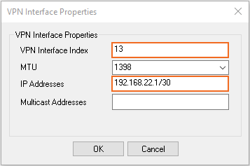
- Click OK. The VPN next hop interface is listed in the VPN Next Hop Interface Configuration table.

- In the VPN Interface Index field, enter a number between
- Click Send Changes and Activate.
Step 2. Add the VPN Interface IP to the Shared IP Addresses
Introduce the IP address of the VPN next hop interface on the firewall.
- Go to CONFIGURATION > Configuration Tree > Box > Network.
- In the left menu, select IP Configuration.
- Click Lock.
- In the Shared Networks and IPs section, click +. The Shared Network and IPs window opens.
- Select the virtual Interface.
- In the Network Address field, enter the network the virtual interface resides in.
- In the Shared IPs in this Network table, click + and add the intermediary VPN IP address of the VPN interface. E.g., 192.168.22.1 for the local firewall or 192.168.22.2 for the remote firewall.
- Click OK.
- Click Send Changes and Activate.
Step 3. Configure the Site-to-Site VPN Settings
Configure a site-to-site VPN IPsec tunnel including the VPN next hop interface.
- Go to CONFIGURATION > Configuration Tree > Box > Assigned Services > VPN-Service > Site to Site.
- Click Lock.
- Click the IPsec IKEv1 Tunnels tab.
- Right-click the table under the IPsec IKEv1 Tunnels tab and then select New IPsec IKEv1 tunnel.
- In the IPsec IKEv1 Tunnel window:
- In the Local Networks tab, enter:
- Local IKE Gateway – Enter the local public IP address the VPN service is listening on.
- Network Address – Add the intermediary VPN subnet. E.g.,
192.168.22.0/30
- In the Remote Networks tab, enter:
- Remote IKE Gateway – Enter the remote public IP address the remote VPN service is listening on.
- Network Address – Add the intermediary VPN subnet. E.g.,
192.168.22.0/30
Click the Peer Identification tab and then enter a passphrase the Shared Secret.
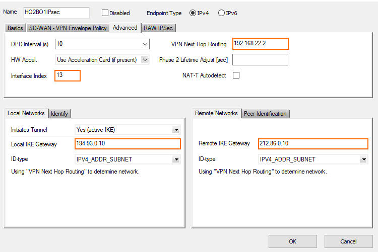
- Click the Advanced tab and enter:
- VPN Next Hop Routing – Enter the IP address of the remote (opposite) VPN next hop interface. E.g.,
192.168.22.2for the local firewall or192.168.22.1for the remote firewall.
- Interface Index – Enter the interface number of the VPN next hop interface configured in Step 1. E.g.
13
- VPN Next Hop Routing – Enter the IP address of the remote (opposite) VPN next hop interface. E.g.,
- Click OK.
- In the Local Networks tab, enter:
- Click Send Changes and Activate.
Step 4. Configure the BGP Service
Enable and configure the BGP service. Configure the remote VPN interface IP address as a BGP neighbor to dynamically learn the routes of the neighboring network.
Step 4.1 Configure which Routes to Propagate into BGP
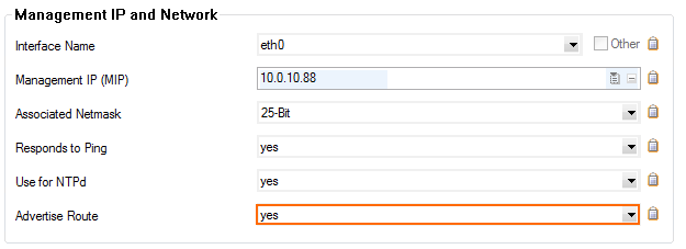
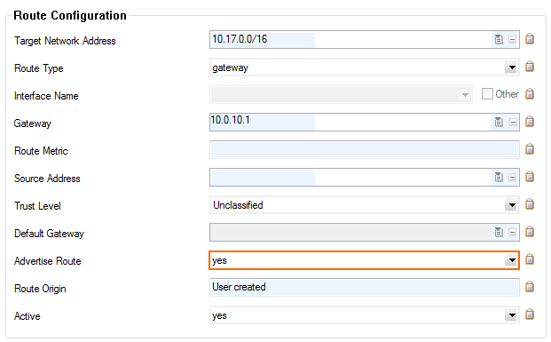
You can either enter the networks you want to propagate manually, or set the Advertise Route parameter to yes for routes you want propagated.
- Go to CONFIGURATION > Configuration Tree > Box > Network.
- Click Lock.
- To propagate the management network, set Advertise Route to yes in the Management IP and Network section.
- In the left menu, click on Routing.
- Double-click on the directly attached routes and gateway routes you want to propagate. The Routes window opens.
- Set Advertise Route to yes and click OK.
- Click Send Changes and Activate.
Step 4.2 Configure the BGP Router
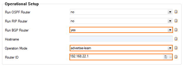
- Go to CONFIGURATION > Configuration Tree > Box > Assigned Services > OSPF-RIP-BGP-Service > OSPF/RIP/BGP Settings.
- Set Run BGP Router to Yes.
- (optional)To learn routes from the remote ASN, set Operation Mode to advertise-learn.
- Enter the Router ID. Typically the local VPN next hop interface IP address is used. E.g.,
192.168.22.2for the local firewall192.168.22.1for the remote firewall.
- In the left menu, click BGP Router Setup.
- Enter the AS Number. E.g.,
64577for the local firewall or64579for the remote firewall Enter the Terminal Password. Use this password if you must directly connect to the dynamic routing daemon via command line for debugging purposes.

- To propagate the directly attached and gateway routes configured in Step 1, set Connected Routes to yes.

- (alternative) To manually enter the networks you want to propagate, click + in the Networks table, and enter the network. E.g.,
172.16.0.0/24

- Click Send Changes and Activate.
Step 4.3. Add a BGP Neighbor
To dynamically learn the routing of the neighboring network, set up a BGP neighbor for the remote VPN next hop interface.
- In the left menu of the OSPF/RIP/BGP Settings page, click Neighbor Setup IPv4.
Click Lock.
Next to the Neighbors table, click the plus sign (+) to add a new neighbor.
- Enter a Name for the neighbor and click OK. The Neighbors window opens.
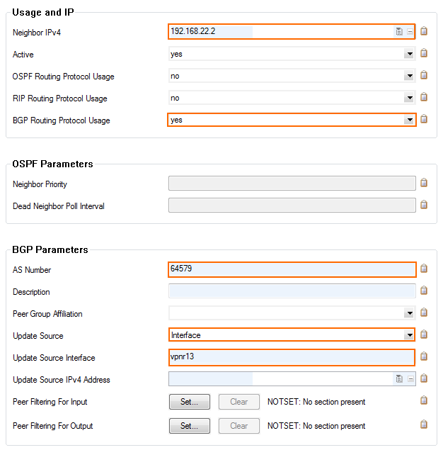
Configure the following settings in the Usage and IP section:
- Neighbor IPv4 – Enter the remote address for the VPN next hop interface. E.g.,
192.168.22.2for the local firewall192.168.22.1for the remote firewall.
- OSPF Routing Protocol Usage – Select no.
- RIP Routing Protocol Usage – Select no.
- BGP Routing Protocol Usage – Select yes.
- Neighbor IPv4 – Enter the remote address for the VPN next hop interface. E.g.,
In the BGP Parameters section, configure the following settings:
AS Number – Enter the ASN for the remote network. E.g.,
64579for the local firewall64577for the remote firewall.
Update Source – Select Interface.
Update Source Interface – Enter the VPN next hop interface in the format:
vpnr<interface number>. E.g.,vpnr13
- Click OK.
- Click Send Changes and Activate.
Step 5. Verify the BGP Service Configuration
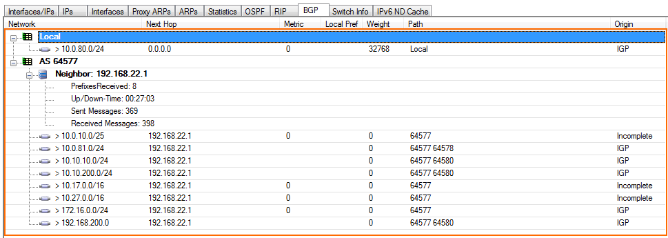
On the CONTROL > Network page, verify that BGP routes are learned. Click the BGP tab and expand the relevant AS tree. It can take up to three minutes for new routes to be learned.
Local Firewall Network > BGP page:

Remote Firewall Network > BGP page:
