If you are running multiple virtual routers on your CloudGen Firewall, each virtual router instance can be configured independently of any other one. Because the VPN service is available only to the default router, the traffic managed by an additional virtual router instance must be handed over to the VPN service running in the default router so that it can be encapsulated into the VPN TINA tunnel. This is achieved by a VPN interface index that binds the tunnel configuration and the traffic from the additional virtual router instance to the VPN interface running on the default router.

In the following example, a VPN TINA tunnel is used for forwarding traffic between two private networks that are located behind a local and a remote firewall. The local firewall actively initiates a TINA tunnel while the remote firewall passively listens for tunnel connection requests.
The first private network (192.168.0.0/24) is attached to an interface on the local firewall. This interface is managed by an additional virtual router instance (VR01). The second private network (192.168.1.0/24) is attached to an interface on the remote firewall. This interface is also managed by an additional virtual router instance (VR01). Both public IPs of the VPN TINA tunnel are managed by the default router. A client PC sends ping messages to the router address of the private network on the remote firewall (192.168.1.254).
Although not required, it is recommended for a better overview to use the same number for the VPN interface index as the number of your additional virtual router. For example, VR01 should correspond to a VPN interface index equal to 1.
Before You Begin
- Configure an additional virtual router instance on both the local and remote firewall. For more information, see Virtual Routing and Forwarding (VRF) and How to Configure and Activate a Virtual Router Instance with Hardware, Virtual, VLAN or Bundled Interfaces.
- Configure the VPN service for general operation. For more information, see How to Assign Services.
Create a VPN Interface on the Local and Remote Firewall
Execute the following steps for both the local and remote firewall. Start with the local firewall.
- Go to CONFIGURATION > Configuration Tree > Box > your local firewall > Assigned Services > VPN > VPN Settings.
- Click Lock.
- In the left menu, select Routed VPN.
Next to the Interface Configuration table, click Add. The VPN Interface Properties window opens.
- For VPN Interface Index, enter a number. For a better overview, always use the same number as the number of your additional virtual router. For example, in case your router instance name is VR01, enter
1.
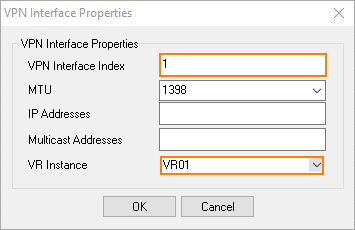
- From the VR Instance list, select your virtual router instance, e.g., VR01.
- Click OK.
- Click Send Changes and Activate.
If not yet done, repeat the previous steps on the remote firewall.
Create a VPN TINA Tunnel on the Local Firewall
- Go to CONFIGURATION > Configuration Tree > Box > your local firewall > Assigned Services > VPN > Site to Site.
- Click Lock.
- Select TINA Tunnels.
- Right-click and select New TINA tunnel... from the list.
- In the TINA Tunnel window, enter a name for the TINA tunnel.
- In the Name field, enter the name for the new VPN tunnel.
- (IPv6 only) Select the IPv6 check box.
- Configure the Basics TINA tunnel settings to match the settings configured for the local firewall.
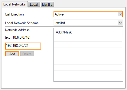
- In the Local Networks tab, select the Call Direction to Active.
- For the Network Address, enter the network address of the private network behind the local firewall, e.g.,
192.168.0.0/24. - Click Add.
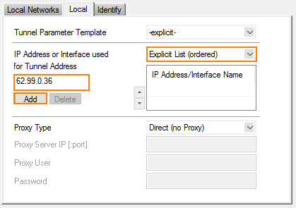
- Click the Local tab and select Explicit List (ordered) from the list.
- Enter the IP address or Interface used for Tunnel Address.
- Click Add.
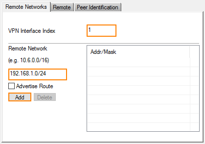
- In the Remote Networks tab, enter 1 for the VPN Interface Index.
- For the Remote Network, enter the network address for the private network behind the remote firewall, e.g.,
192.168.1.0/24.
- Click Add.
- Click the Remote tab and enter the Remote Peer IP Address, e.g.,
212.86.0.10.
- Click Add.
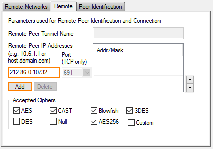
- Click OK to leave the TINA Tunnel window.
- When you are informed that the identification information between the two sites has not been set, click OK to proceed. This information will be configured in a following step.
Create a VPN TINA Tunnel on the Remote Firewall
- Go to CONFIGURATION > Configuration Tree > Box > your remote firewall > Assigned Services > VPN > Site to Site.
- Click Lock.
- Select TINA Tunnels.
- Right-click and select New TINA tunnel... from the list.
- In the TINA Tunnel window, enter a name for the TINA tunnel.
- In the Name field, enter the name for the new VPN tunnel.
- (IPv6 only) Select the IPv6 check box.
- Configure the Basics TINA tunnel settings to match the settings configured for the remote firewall.
- In the Local Networks tab, select the Call Direction to Passive.
- For the Network Address, enter the network address of the private network behind the local firewall, e.g.,
192.168.1.0/24. - Click Add.
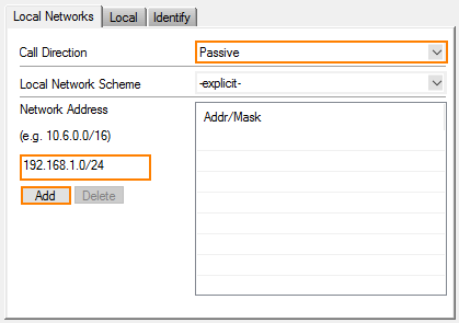
- Click the Local tab and select Explicit List (ordered) from the list.
- Enter the IP address or Interface used for Tunnel Address, e.g.
212.86.0.10.
- Click Add.
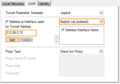
- In the Remote Networks tab, enter 1 for the VPN Interface Index.
- For the Remote Network, enter the network address for the private network behind the remote firewall, e.g.,
192.168.0.0/24.
- Click Add.
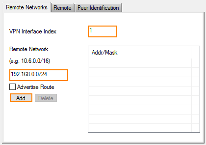
- Click the Remote tab and enter the Remote Peer IP Address, e.g.,
62.99.0.36.
- Click Add.
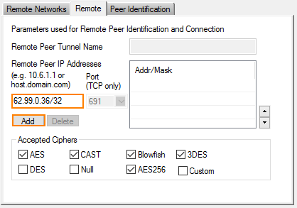
- Directly proceed with the next step without leaving the displayed window.
Exchange the Public Keys Between the Local and Remote Firewall
Start with exporting the public key in the displayed window on the remote firewall.
- Click the Identify tab.
- Click Ex/Import.
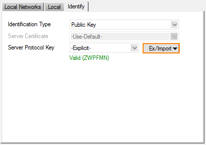
- In the menu, click Export Public Key to Clipboard.
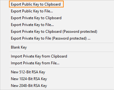
- Click OK to close the TINA Tunnel window.
- Go to CONFIGURATION > Configuration Tree > Box > your local firewall > Assigned Services > VPN > Site to Site.
- Click Lock.
- Select TINA Tunnels.
- Double-click the entry for the VPN tunnel.
- The TINA Tunnel window is displayed.
- Click the Peer Identification tab.
- Click Ex/Import.
- In the menu, click Import Private Key from Clipboard.

- Click the Identify tab.
- Click Ex/Import.
- In the menu, click Export Public Key to Clipboard.
- Click OK to close the TINA Tunnel window.
- Go to CONFIGURATION > Configuration Tree > Box > your remote firewall > Assigned Services > VPN > Site to Site.
- Click Lock.
- Select TINA Tunnels.
- Double-click the entry for the VPN tunnel.
- The TINA Tunnel window is displayed.
- Click the Peer Identification tab.
- Click Ex/Import.
- In the menu, click Import Private Key from Clipboard.
- Click OK to close the TINA Tunnel window.
Verify that the VPN TINA Tunnel is up
- Log into your local firewall.
- Go to VPN > Site-to-Site.

- Log into your remote firewall.
- Go to VPN > Site-to-Site.

Create an Access Rule for the Local and Remote Firewall to let VPN Traffic Pass
Traffic originating from the private network behind the local firewall must be able to reach the private network behind the remote firewall. The access rule must be configured to be Bi-Directional. In order to forward traffic from the interfaces that are assigned to the additional virtual router instance, the access rule must be applied to this virtual router instance, e.g., VR01. The access rule must be created on both the local firewall and the remote firewall.
- On the local firewall, go to CONFIGURATION > Configuration Tree > Box > your local firewall > Assigned Services > Firewall > Forwarding Rules.
- The Forwarding Rules window is displayed.
- Click Lock.
- Click + to add a new access rule.
- For the access rule type, select Pass.
- Enter the name for the access rule, e.g., VPN-S-2-S.
- Click Bi-Directional.
- Select the virtual router instance for Source VR Instance and Destination VR Instance, e.g., VR01.
- For Source, click <explicit-src> from the list, and enter the network address for the private network behind the local firewall, e.g.,
192.168.0.0/24. - For Service, select Any from the list.
- For Destination, click <explicit-src> from the list, and enter the network address for the private network behind the remote firewall, e.g.,
192.168.1.0/24. - For the Connection Method, select Original Source IP.
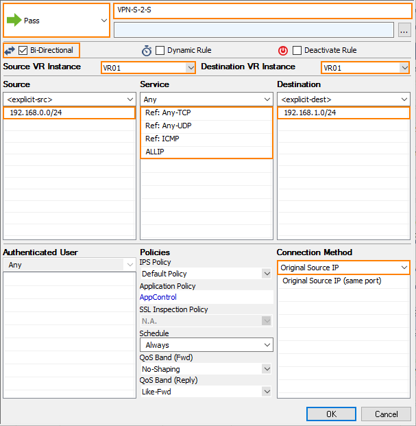
- Click OK.
Repeat the previous steps for the remote firewall.
Verify that the Virtual Tunnel is Forwarding Traffic
- Attach a client host to the private network behind the local firewall, and configure the standard route pointing to the interface that is managed by the additional virtual router instance, e.g., 192.168.0.254.
- Start sending ping messages to the gateway address interface on the remote firewall that is managed by the additional virtual router instance, e.g., 192.168.1.254.
- On the local firewall, go to FIREWALL > Live.
- Set the filter for Src. VR Instance to the name of your additional virtual router instance, e.g., VR01.

- In the column Output-IF, the firewall displays the name of the VPN tunnel connection, e.g., vpn1@FW2FW-..... Note that the number 1 is part of vpn1@..., indicating the VPN Interface Index that was set to 1 at the beginning. The client PC is sending ping messages from its IP address 192.168.0.1.
- On the remote firewall, go to FIREWALL > Live.
- Set the filter for Dst. VR Instance to the name of your additional virtual router instance, e.g., VR01.

- In the column Interface, the firewall displays the name of the VPN tunnel connection, e.g., vpn1@FW2FW-..... Note that the number 1 is part of vpn1@..., indicating the VPN Interface Index that was set to 1 at the beginning. The column Output-IF displays the name of the VPN tunnel, e.g., vpn1.
(Optional) Verify that a Client Host on the Remote Private Network can be Reached
- Attach a client host to the private network behind the remote firewall and configure its IP address, e.g., 192.168.1.1.
- Ensure that there is no local firewall running on the client host. If so, disable the firewall completely on the client host so that all packages can reach the client host.
- Start sending ping messages from the local client host to the remote client host: On your client host, enter
ping 192.168.1.1 - On the remote firewall, go to FIREWALL > Live.
- Set the filter for Dst. VR Instance to the name of your additional virtual router instance, e.g., VR01.

- In the column Interface, the firewall displays the name of the VPN tunnel connection, e.g., vpn1@FW2FW-. Note that in this case the access rule is now VPN-S-2-S, which indicates that the ping packages are now forwarded from the VPN service on the remote firewall to the remote client host while traversing the interface eth3 on the virtual router VR01.
