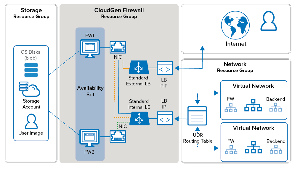
Configure a high availability cluster to ensure that the services running on the Barracuda CloudGen Firewall VMs are always available even if one unit is unavailable due to maintenance or a hardware issue. To be able to configure an HA cluster, both firewalls VMs must be deployed to the same subnet and be placed in either an Availability Set or Availability Zone (where available). This ensures that the VMs are placed in different fault and update domains inside the Azure data center. Incoming connections are forwarded to the active firewall by the Azure Load Balancer. The load balancer actively monitors the services on the firewall and, when an HA failover takes place, redirects the traffic to the other, now-active firewall. You must create load balancer rules and health probes for each service for the load balancer to know which ports to forward and how to monitor them. The load balancer does not fail over immediately after the service has failed over, since it requires at least two probes to fail before reacting. Combined with the minimum poll time of 5 seconds, this means that failover will take at least 10 seconds during which no traffic can be forwarded.
The standard load balancer allows stateful sessions to remain as there are no IP address changes with this method. The backend VMs are configured to use the firewall as the default gateway and, if needed, access control between the backend subnets using Azure user-defined routing. Because only one IP address can be configured as the destination, a Standard type internal load balancer IP address is used, and this load balancer directs traffic to the active firewall. Now, the backend VMs can connect via the active firewall to the Internet.
Step 1. Deploy Two CloudGen Firewall VMs
To configure an HA cluster, deploy two CloudGen VMs. The public IPs attached to the NICs are removed after configuring client-to-site VPN access via the load balancer. To be able to use them in an HA cluster, the deployment must meet the following requirements:
- Static private (internal) IP addresses must be used.
- The SKU of the public IP of each firewall must match the SKU of the load balancer. In this case, the public IP must have a standard SKU since a standard load balancer will be used.
- The same instance size for both VMs must be used.
- Both firewalls must be the same Barracuda CloudGen Firewall for Azure model.
- Both VMs must be deployed in one Availability Set or across Availability Zones.
For more information, see How to Deploy a CloudGen Firewall from the Microsoft Azure Marketplace or How to Deploy a CloudGen Firewall in Microsoft Azure Using PowerShell and ARM.
Official templates are available to assist you to deploy quicker. These can be found in our GitHub: https://github.com/barracudanetworks/ngf-azure-templates . If you are using the GitHub template, provisioning may take a while. Until it completes, you will get the error message "access denied" if you try to connect via Barracuda Firewall Admin. If boot diagnostics are enabled, you can view the log. Further deployment examples can be found in the contrib folder.
To test, you can deploy a stand-alone proof of concept environment by following this guide: https://app.barracuda.com/resource/ref_architectures/azure_high_availability_cluster
Step 2. Change the Firewall Network Configuration to Use the Static Private IP Addresses
On both firewall VMs, change the network configuration to use a static network interface. Use the static private IP address you assigned to the NIC during deployment.
Step 2.1 Reconfigure the Network Interface
Change the network interface type from dynamic to static.
- Go to CONFIGURATION > Configuration Tree > Box > Network.
- In the left menu, click xDSL/DHCP.
- Click Lock.
- If present, delete the DHCP01 entry in the DHCPv4 Links list.
- Expand the DHCPv4 Enabled drop-down list and select No.
- Click Send Changes.
- In the left menu, click IP Configuration.
- In the Management Network and IPs section, select eth0 from the Interface list.
- Enter the static internal IP address from Step 1 as the Management IP. E.g.,
10.0.20.6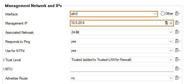
Step 2.2 Create the Default Route
Add the default route. The default gateway in Azure subnets is always the first IP in the subnet. E.g., 10.0.20.1 if the subnet is 10.0.20.0/24.
- In the left menu, click Advanced Routing.
- Click + in the IPv4 Routing Table and configure the following settings:
- Name – Enter a descriptive name for the route and click OK.
- Target Network Address – Enter
0.0.0.0/0 - Route Type – Select gateway.
- Gateway – Enter the first IP address of the subnet the firewalls reside in. E.g.,
10.0.20.1if the IP addresses of the firewalls are 10.0.20.6 and 10.0.20.7. - Trust Level – Select Unclassified.
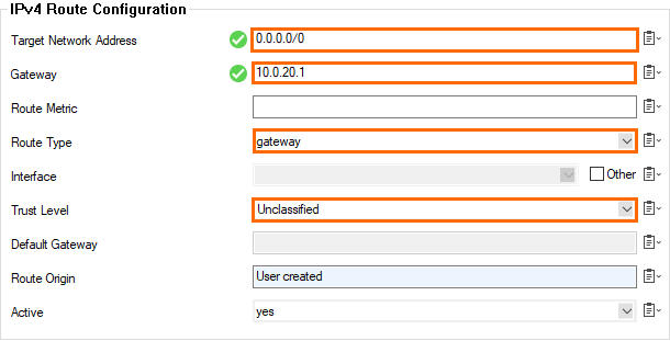
- Click OK.
- Click Send Changes and Activate.
Step 2.3 Disable ICMP Monitoring of the Gateway
ICMP probing must be disabled for the interface.
- Go to CONFIGURATION > Configuration Tree > Infrastructure Services > Control.
- Click Lock.
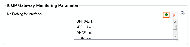
- In the ICMP Gateway Monitoring Parameter section, click + to add an entry to the No Probing for Interface table.
- In the Other field, enter
eth0.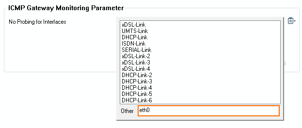
- Click Send Changes and Activate.
Step 2.4 Activate the Network Changes
Activate the changes to the network configuration.
- Go to CONTROL > Box.
- In the Network section of the left menu, click Activate new network configuration.
- Click Failsafe.
Open the CONTROL > Network page. Your interface and IP address are now static.
Step 3. (PAYG only) Import PAYG Licenses from the Secondary Firewall
Step 3.1 Export the PAYG license from the Secondary Firewall
- Log into the secondary firewall.
- Go to CONFIGURATION > Configuration Tree > Box > Box Licenses.
- Click Lock.
- Select the license file, click Export, and select Export to File.
- Click Unlock.
Step 3.2 Import the PAYG License on the Primary Firewall
- Log into the primary firewall.
- Go to CONFIGURATION > Configuration Tree > Box > Box Licenses.
- Click Lock.
- Click + and select Import from Files.
- Select the license file exported from the secondary firewall.
- Click OK.
- Select I agree to accept the terms and conditions.
- Click OK.
- Click Send Changes and Activate.
The primary firewall now has both PAYG licenses listed in the Licenses list.
Step 4. Configure an HA Cluster on the CloudGen Firewall VMs
Configure the two firewalls to synchronize session and configuration information. Use Application Redirect access rules to redirect incoming traffic from the eth0 interface to the services. Use the internal IP address of the primary and secondary firewall as the destination of the rule to ensure that it matches without regard to which firewall VM the service is currently running on.
For more information, see How to Set Up a High Availability Cluster.
Step 5. (BYOL only) Activate and License the two Firewall VMs
Activate the license on the secondary firewall, then on the primary firewall. If the primary unit is activated prior to the secondary unit, the licenses for the secondary cannot be downloaded. In this case, reboot the primary firewall, perform a complete manual HA sync, and update to download and install the licenses correctly.
For more information, see How to Activate and License a Standalone High Availability Cluster.
Step 6. Disassociate the Public IP Addresses
When both a load balancer and a public IP are available for the firewall VM, the public IP is used as the default source IP address for the VM. This means that outgoing connections use different source IP addresses depending on which firewall is active.
Using the Azure Web Portal
For each firewall VM, remove the public IP address from the network interface.
- Go to https://portal.azure.com.
- Locate the Network Interface attached to your primary firewall VM.
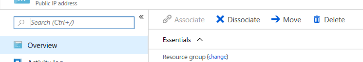
- Click Public IP Address. The Public IP address column opens.
- Click Disassociate.
- Repeat for the secondary firewall VM.
Step 7. Create the External Load Balancer
After you have deployed the two firewalls, you can create the load balancers that will direct traffic as required. You will need to create a new external and internal load balancer to handle all potential traffic flows.
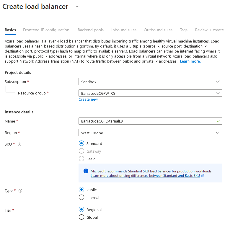
Step 7.1 Configure the Basic Settings
From the Azure portal:
- Under Azure services, click the + symbol to Create a resource.
- Type in
Load Balancerand select the resource from the list. The Load Balancer page opens.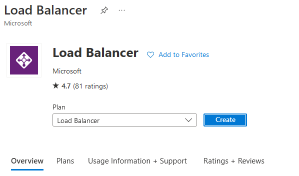
- Click Create.
- On the next page, configure the following settings:
Name – Enter the name of the External Load Balancer.
- Region – Select your region.
SKU – Select the Standard SKU.
Type – Select the Public type.
Tier – Select your tier.
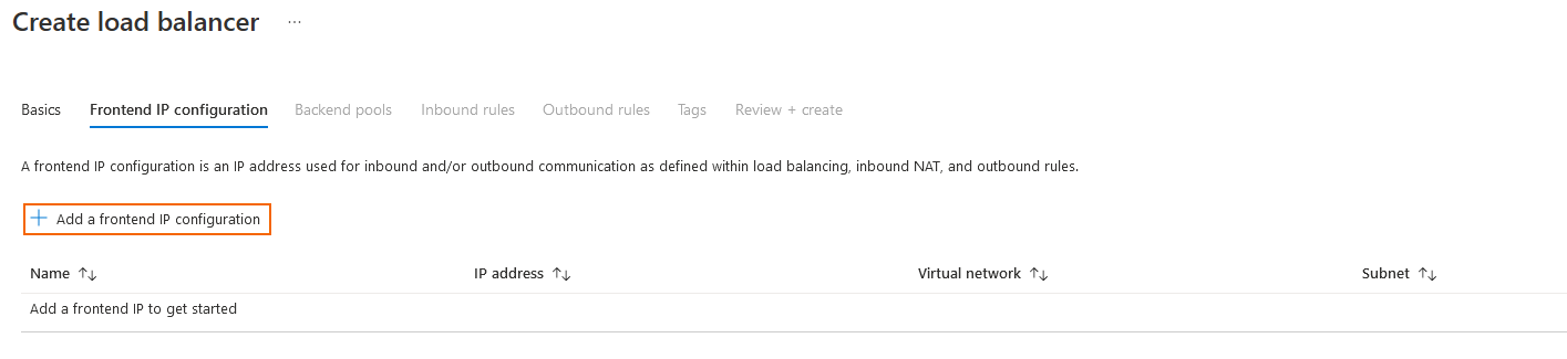
Step 7.2 Add a Frontend IP Configuration
Click Next: Frontend IP configuration.
Click + to Add a frontend IP configuration.
On the next page, enter the Name of the frontend IP.
Select an existing Public IP address or create a new public IP address.
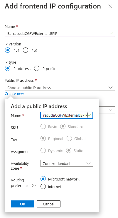
Click Add.
The entry is now displayed in the list.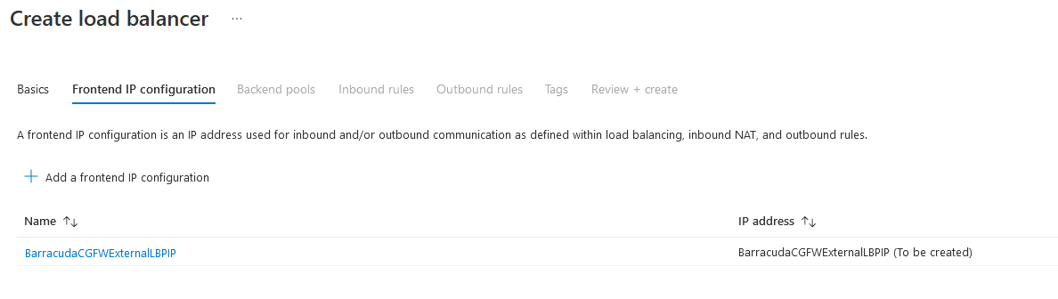
Step 7.3 Add a Backend Pool
- Click Next: Backend pools.
Click + to Add a backend pool.
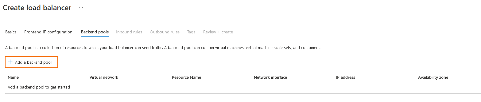
- Complete the fields as below:
- Name – Enter your desired name for the backend pool.
- Virtual Network – Select the virtual network you built your firewalls in.
- Backend Pool Configuration – Select IP address.
IP address – Select the CGF IP addresses where you wish the LB to send traffic to.
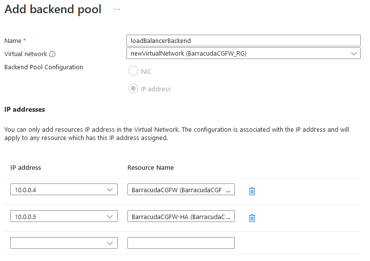
Repeat for the second firewall VM you built.
Click Add.

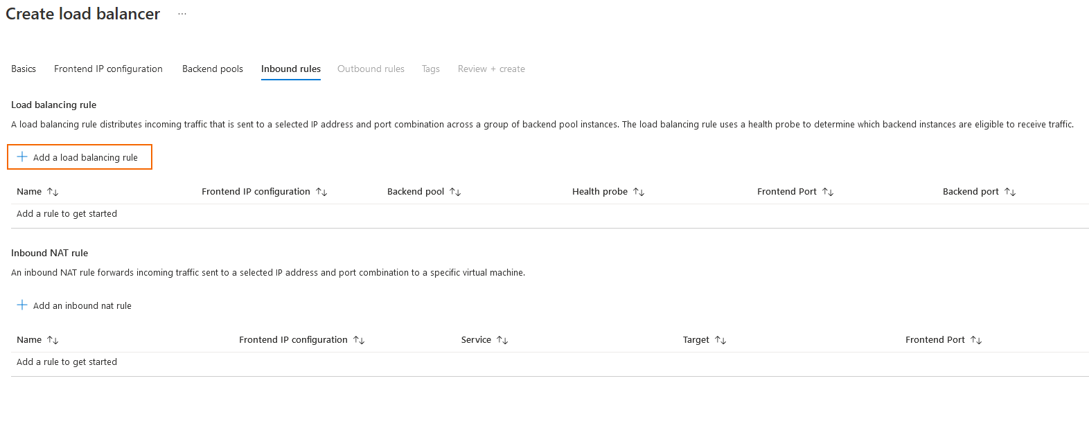
Step 7.4 Add an Inbound Rule
To create the load balancing rules for incoming traffic, you must create one for TCP and one for UDP so that the firewalls can forward traffic over these ports from the Internet. This instruction creates rules for inbound client VPNs that meet this requirement.
- Click Next: Inbound rules.
- Click + to Add a load balancing rule to create a new rule.
- Configure the settings as below:
- Name – Suggested name:
TINA-TCP - IP Version – IPv4
- Frontend IP address – Select the front-end IP created at build time.
- Backend pool – Select the backend pool just created.
- Protocol – TCP
- Port –
691 - Backend port –
691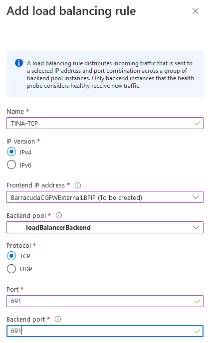
- Health probe – Select a probe created previously, or click Create new to create a new one:
- Name – Suggested name:
CGFHealthProbe - Protocol – TCP
- Port –
65000 - Interval – Leave as default.
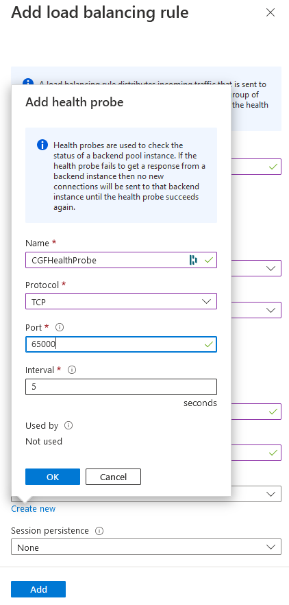
- Name – Suggested name:
- Click OK to create the health probe.
- Session persistence – Leave as default (None).
- Idle timeout (minutes) – Leave as default (
4). - TCP reset – Leave as default (Disabled).
- Floating IP – Leave as default (Disabled).
- Outbound source network address translation (SNAT) – Leave as default ((Recommended) Use outbound rules to provide backend pool members access to the Internet.).
- Name – Suggested name:
- Click Add to create the load balancing rule.
Repeat the steps above to create a second rule for UDP, but change the following settings:
- Name – Suggested name:
TINA-UDP - Protocol – UDP
- Port –
691 - Backend port –
691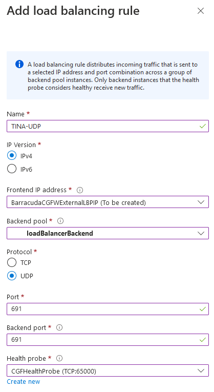
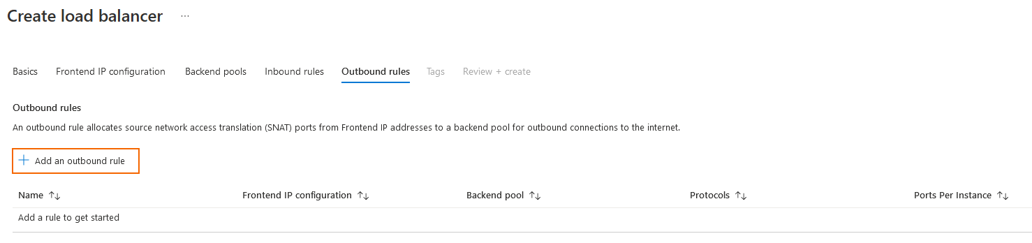
Step 7.5 Add an Outbound Rule
To create the load balancing rules for outbound traffic, you must have for minimum one rule in order for the firewalls to pass traffic out to the Internet. This instruction creates an Any rule for outbound traffic that meet this requirement.
- Click Next: Outbound rules.
- Click + to Add an outbound rule.
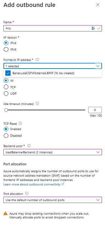
Configure the settings as below:
- Name – Suggested name:
Any - IP Version – IPv4
- Frontend IP address – Select the front-end IP created at build time.
- Protocol – All
- Idle timeout (minutes) – Leave as default (
4). - TCP reset – Leave as default (Enabled).
- Backend pool – Select the backend pool just created.
- Port allocation – Use the default number of outbound ports.
- Name – Suggested name:
- Click Add.
The rule is now displayed in the list.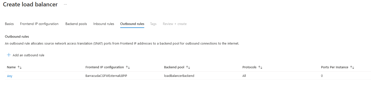
Step 7.6 Create the Load Balancer
- Click Next: Tags.
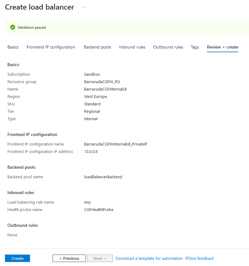
Click Next: Review + create.
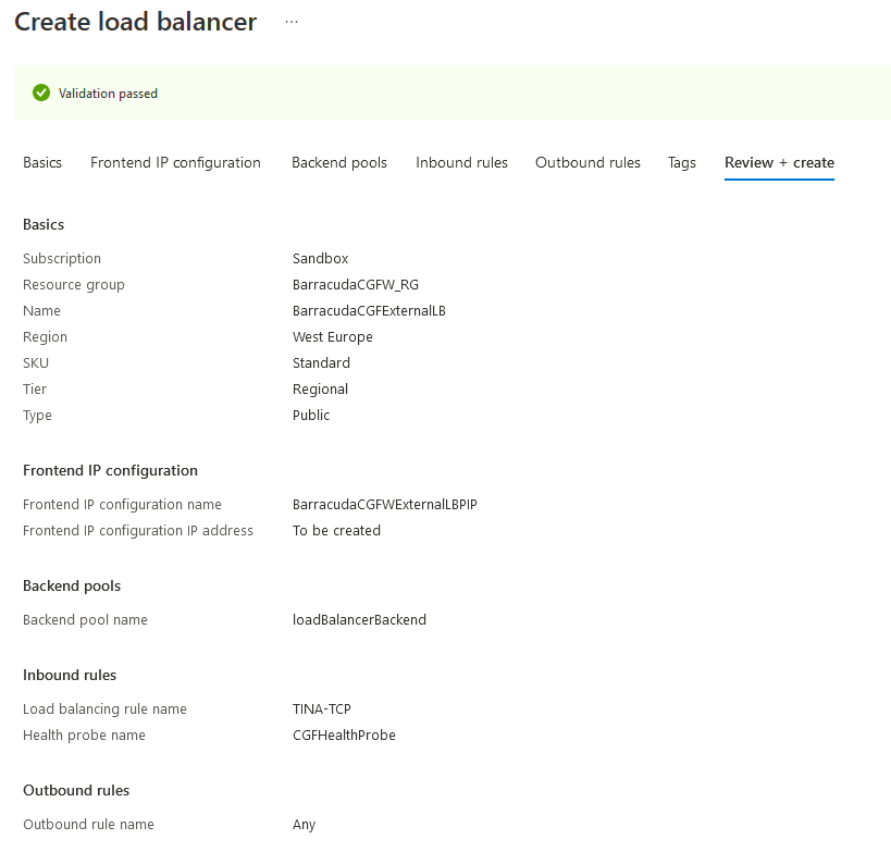
Review your settings and click Create.
Step 8. Create the Internal Load Balancer
The internal load balancer is essential for a standard load balancer HA design because it is the destination for all user-defined routes.
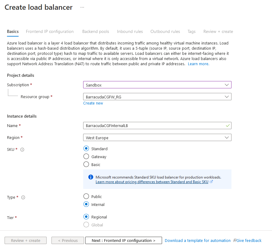
Step 8.1 Configure the Basic Settings
From the Azure portal:
- Under Azure services, click the + symbol to Create a resource.
- Type in
Load Balancerand select the resource from the list. The Load Balancer page opens.
- Click Create.
- On the next page, configure the following settings:
Name – Enter the name of the Internal Load Balancer.
- Region – Select your region.
SKU – Select the Standard SKU.
Type – Select the Internal type.
Tier – Select you tier.
Step 8.2 Add a Frontend IP Configuration
- Click Next: Frontend IP configuration.
- Click + to Add a frontend IP configuration.
On the next page, configure the following settings:
Name – Enter the name of the frontend IP.
- Virtual Network – Select the virtual network your firewalls are in.
- Subnet – Select the subnet the firewalls are in.
- IP Address assignment – Select Static.
- Private IP address – Enter a private IP in that subnet for the load balancer to use.
- Availability Zone– Select Zone-redundant.
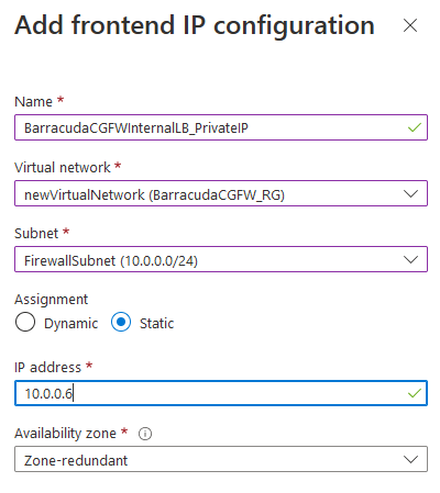
Click Add.
The entry is now displayed in the list.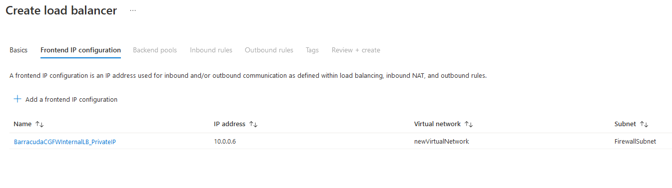
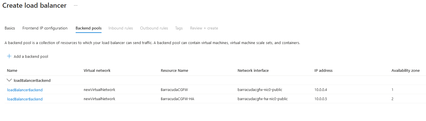
Step 8.3 Add a Backend Pool
Click Next: Backend pools.
- Click + to Add a backend pool.
- Complete the fields as below:
- Name – Enter your desired name for the backend pool.
- Virtual Network – Select the virtual network you built your firewalls in.
- Backend Pool Configuration – Select IP address.
- IP address – Select the CGF IP addresses where you wish the LB to send traffic to.

Repeat the steps for the second firewall VM you built.
Click Add.
Step 8.4 Add an Inbound Rule
To create the load balancing rules for incoming traffic, you need to enable load balancing for all ports so that the firewalls can check all traffic.
- Click Next: Inbound rules.
- Click + to Add a load balancing rule.
- Configure the settings as below:
- Name – Suggested name:
Any - IP Version – IPv4
- Frontend IP address – Select the front-end IP created at build time.
- HA Ports – Activate HA ports.
- Health probe – Select the probe created previously or click Create new to create a new one:
- Name – Suggested name:
CGFHealthProbe - Protocol – TCP
- Port –
65000 - Interval – Leave as default.
- Click OK to create the health probe.
- Name – Suggested name:
- Session persistence – Leave as default (None).
- Idle timeout (minutes) – Leave as default (
4). - TCP reset – Leave as default (Disabled).
- Floating IP – Leave as default (Disabled).
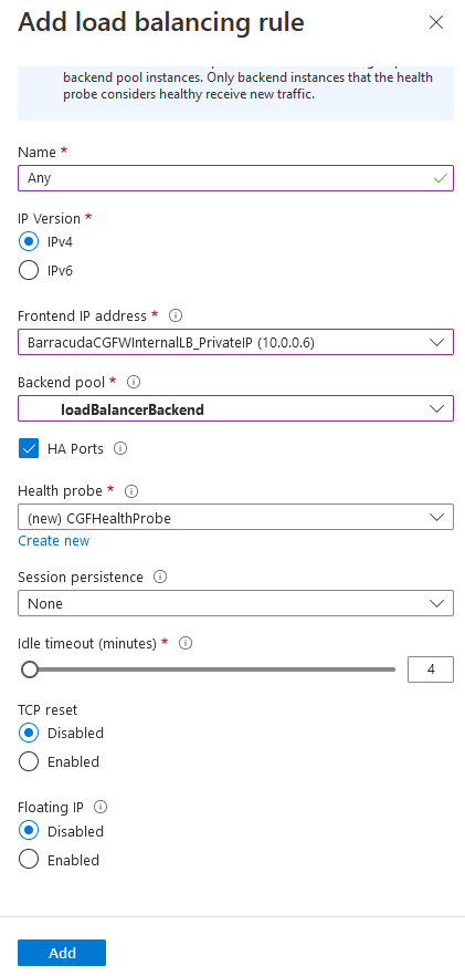
- Name – Suggested name:
- Click Add.
The rule is now displayed in the list.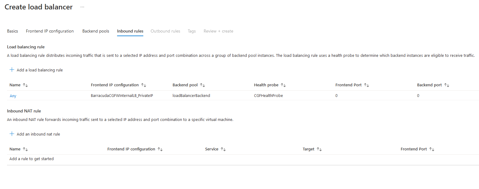
Step 8.5 Create the Load Balancer
Click Next: Outbound rules.
Click Next: Tags.
Click Next: Review + create.
Review your settings and click Create.
Now you have completed the setup of the load balancers.
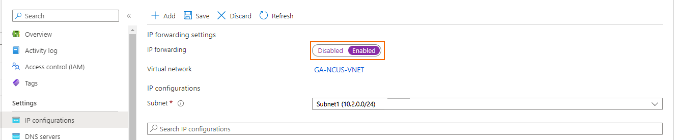
Step 9. Enable IP Forwarding
To allow the firewall to pass traffic not intended for itself, you must update the network interface.
In the Azure portal:
- Go to the virtual machine.
- Go to Networking, and locate the Network Interface attached to the firewall.
- In IP configurations, make sure that IP forwarding is enabled.
For more information, see How to Configure a Client-to-Site VPN Group Policy or How to Configure a Client-to-Site TINA VPN with Personal Licenses .
Step 10. Allow the Load Balancer Health Probes to Succeed
Activate the preconfigured firewall forwarding rule to allow load balancer health probes to succeed. The connection will use the port you indicated in Steps 2 & 3 above. It will originate from 168.63.129.16 and can be redirected to any service running locally on the firewall (e.g., 127.0.0.9:450 for firewall authentication service, or 127.0.0.9:691 for FW TINA VPN).
- Log into the Barracuda CloudGen Firewall with Barracuda Firewall Admin.
- Go to CONFIGURATION > Configuration Tree > Assigned Services > Firewall > Forwarding Rules.
- Click Lock.
- Open the rule
CLOUD-LB-PROBE. - To activate the rule, clear the check box next to Deactivate Rule.

- Click OK.
- Click Send Changes and Activate, then click Activate.
Step 11. Configure User-Defined Routing in Azure
Configure UDR for the backend VMs to use the internal load balancer's IP as their default gateways for all connections to the Internet. 0.0.0.0/0 will only impact traffic that does not have a route already present in Azure. E.g., Internet.
To affect traffic within the VNET, subnet, or peered VNET, introduce routes for a matching destination network. (Check the effective routing of a VM if uncertain what routes are present already).
Step 12. Configure a Client-to-Site VPN for Management Access
Configure a TINA client-to-site VPN that will be used for management access. Connect via the load balancer public IP address.
For more information, see How to Configure a Client-to-Site VPN Group Policy or How to Configure a Client-to-Site TINA VPN with Personal Licenses.
Check the Connection
Use a client-to-site VPN connection to manage both Barracuda CloudGen Firewall VMs via the internal IP addresses. For more information, see Client-to-Site VPN.
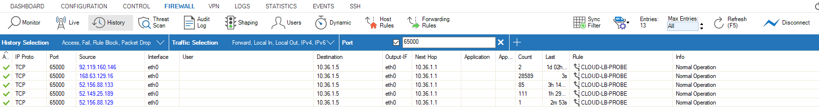
Go to the Firewall > History view and confirm you can see the health probes succeeding. Traffic should be passing through the firewall correctly. If you see timeouts, confirm NSGs on the interfaces permit traffic and that IP Forwarding is enabled.
Example of Successful Monitoring Polls on port 65000