

VPN services on the Control Center are organized in VPN groups. Create VPN tunnels by dragging them between two VPN services. To configure an IPv6 VPN tunnel, both VPN services must support IPv6.
Before You Begin
To use the GTI Editor on the range or cluster level, enable Own VPN GTI Editor in the range or cluster Property Settings.
Configure the GTI settings for the VPN services on the managed CloudGen Firewalls. For more information, see How to Configure VPN GTI Settings for a VPN Service.
To use Dyn Mesh, go to the VPN Settings and verify that Disable Dyn Mesh is set to no for each VPN service.
Step 1. Create a VPN Group
VPN groups contain the default settings for all VPN tunnels in the group and the list of VPN services used to create the tunnels.
Go to CONFIGURATION > Configuration Tree > Multi-Range > Global Settings > VPN GTI Editor.
Click Lock.
Click + to add a new VPN group.

Enter the Name.
Click OK. The Group window opens.
Edit the default TINA settings.
Configure the following optional settings:
Transport – This setting defines the transport protocol to be used and offers the following options:
UDP – Tunnel uses UDP port 691 to communicate. This connection type is best suited for response-optimized tunnels.
TCP – Tunnel uses TCP connection on port 691 or 443 (for HTTP proxies). This mode is required for connection over SOCKS4 or HTTP proxies.
UDP & TCP – Tunnel uses TCP and UDP connections. The tunnel engine uses the TCP connection for UDP requests, and the UDP connection for TCP requests and ICMP-based applications.
ESP – Tunnel uses ESP (IP protocol 50) to communicate. This connection type is best suited for performance-optimized tunnels.
Routing – This transport type is only relevant in combination with SD-WAN configuration. Specifying routing as transport disables data payload encryption within the tunnel. This transport should only be used for uncritical bulk traffic. The transport type Routing activates the parameter Routing Next-Hop in the tunnel configuration dialog, where the next-hop address for routed data packets must be specified. To enter a routing next-hop address when the Direction is Passive, follow these steps:
Select Direction: Active
Select Transport: Routing
Enter the Routing Next-Hop address.
Select Direction: Passive
Encryption – Select the encryption mode required for the tunnel.
Authentication – Select the authentication method.
Dynamic Mesh – Set to yes to use allow the VPN services to create on-demand IPv4 VPN tunnels. For more information, see How to Configure a Dynamic Mesh VPN with the GTI Editor.
Dynamic Mesh Timeout – Enter the number of seconds before a dynamic tunnel is shut down.
SD-WAN Bandwidth Protection – Set to use advanced SD-WAN features such as Performance-Based Transport Selection, or Adaptive Bandwidth Protection. For more information, see SD-WAN.
Advanced – Group node for the following subordinated parameters:
Key Time Limit [min] – Time in minutes after which the re-keying process is started. The default value is 10. This option prevents a connection that uses the same key from being used too long.
Key Traffic Limit – Amount of data after which the re-keying process is started.
Identification Type – Determines the authentication method for the VPN tunnel partners.
Tunnel Probing [sec] – Interval in seconds for probing the VPN tunnel. The default value is 30. If the tunnel partner does not respond within this interval, the value set in 'Tunnel Timeout' is used to terminate the tunnel.
Tunnel Timeout [sec] – Time in seconds after which the tunnel is terminated if tunnel probing fails. The default value is 20.
Packet Balancing – Packet Balancing is used to balance transports over multiple ISP connections. This works only for transports within the same SD-WAN class.
High Performance Settings – Enabling High Performance Settings is useful only on units with multicore processors. This option is used for splitting a VPN TINA tunnel into multiple UDP streams to perform parallel transmission, thereby significantly decreasing transmission time.
This option is only available for the following:
– TINA tunnels + UDP. By default, High Performance Settings is deactivated.
– TINA tunnels + UDP + TCP
WANOpt Policy – To use WAN Optimization, select one of the policies from the drop-down list.
Default IP Version – Select the default IP version used when creating the VPN tunnels or adding transports. To use IPv6, both VPN services must support IPv6 VPN.
Hide in Barracuda Earth – Set to yes to not display these tunnels in Barracuda Earth. This also disables the tunnel icon on the Control Center status page.
Meshed – Set to yes to automatically create a static fully meshed VPN network.
Hub for this Group – If you already added VPN services to the Group, select the VPN hub.
Service Placement – Select Classic circular to automatically arrange all VPN services in a circular pattern. If one service is selected as the VPN hub, it is placed in the center of the circle. User allows the user to arrange the VPN services.
(optional) Click Edit IPSec and edit the default IPsec settings.
Click OK.
Click Send Changes and Activate.
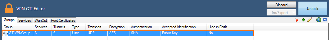
The VPN group is now listed in the Groups tab.
Step 2. Add VPN Services to the VPN Group
Add the VPN services to the VPN group. If you are using the GTI Editor on the range or cluster level, only add VPN services into the VPN group from the range or cluster you are in.
Go to CONFIGURATION > Configuration Tree > Multi-Range > Global Settings > VPN GTI Editor.
Click Lock.
In the Group tab, click on the VPN group. The VPN group name is displayed in the top status bar of the GTI map.

Click on the Services tab.
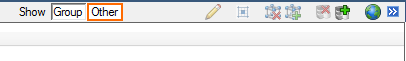
To display the available VPN services, click Other on the top right.
For each VPN service you want to add to the VPN group:
Right-click on the VPN service
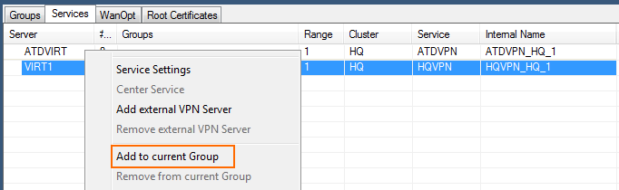
Click Add to current Group. The VPN service is added to the map area below.
Click Send Changes and Activate.
Step 3. Create a VPN Tunnel
Create VPN tunnels by dragging connections from one VPN service to the other. By default, the VPN service you start with is the active unit, the destination the passive unit. This can be changed in the tunnel configuration settings.
Go to CONFIGURATION > Configuration Tree > Multi-Range > Global Settings > VPN GTI Editor.
Click Lock.
In the Group tab, click on the VPN group. The VPN group name is displayed in the top status bar of the GTI map.
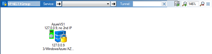
Click on the Server tab. In the GTI map area, the VPN services icons in the VPN are displayed.
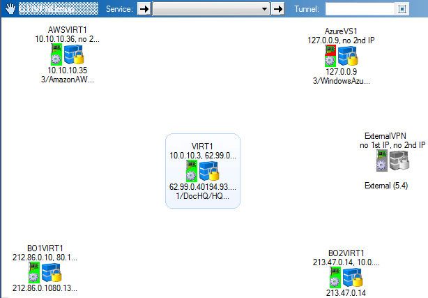
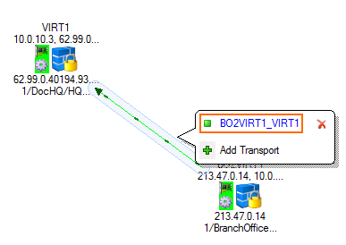
Create a VPN tunnel by dragging from the active VPN service to the passive VPN service. A line is displayed between the VPN services.
Click on the connection between the two VPN services, and click on the transport you want to edit. By default, TINA VPN tunnels are created with one transport.
You can now modify the VPN tunnel as needed:
IP Version – Select IPv4 or IPv6. To use IPv6, both VPN services must support it.
Direction – You can create VPN tunnels using the following modes: active-active, active-passive, on-demand.
Transport Source IP/Interface – If needed, you can modify the transport source IP.
Providers that have been configured by a name in CONFIGURATION > Configuration Tree > Network > IP Configuration > Shared Networks and IPs will be listed by their name in the list.Transport Listening IP/Interface – If needed, you can modify the transport listening IP.
Local Network – If needed, modify the networks that are available through this VPN tunnel.
Click Send Changes and Activate.
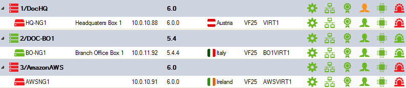
You can view the collective state of all GTI VPN tunnels on the Status page of the Control Center.
Step 4. Create Access Rules to Allow VPN Traffic
You must create access rules on both firewalls involved in the VPN tunnel to allow traffic in and out of the VPN tunnel.
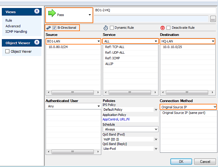
Example access rule for a VPN tunnel from Branch Office 1 (BO1) to Headquarters (HQ). The access rules need to be added to the BO1 and HQ forwarding firewall:
Action – Select PASS.
Bi-Directional – Select the check box.
Source – Select the network object for the BO1 LAN.
Service – Select ALL.
Destination – Select the network object for the HQ LAN.
Connection Method – Select Original Source IP.
Next Steps
You can use the GTI Editor to configure a dynamic mesh. For more information, see How to Configure a Dynamic Mesh VPN with the GTI Editor.
You can use the GTI Editor to configure additional transports using SD-WAN. For more information, see How to Configure SD-WAN Using the VPN GTI Editor.
You can use the GTI Editor to configure traffic shaping for the VPN tunnels. For more information, see Traffic Shaping.