

This article provides a reference for deploying a Barracuda Link Balancer under the following conditions:
- In transparent (firewall-disabled) mode in front of a Cisco ASA firewall that is an endpoint for a site-to-site VPN tunnel.
- In firewall-enabled mode as a remote VPN endpoint with the Cisco ASA on the other end.
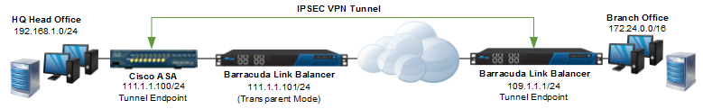
This example combines both scenarios. That is, assume a corporate headquarters with an existing Cisco ASA device and a branch office in Michigan. To improve the network uptime and resilience, the company installs a Barracuda Link Balancer at both sites. At headquarters it is deployed in transparent (firewall-disabled) mode upstream of the Cisco ASA device. In Michigan, it is deployed in firewall-enabled mode.
Before You Begin
Before proceeding, please collect all information in the table below that is valid for your setup. The example values in the table are used in this article.
| Corporate Headquarters (uses Cisco ASA) | ||
|---|---|---|
| 1 | Unused Public IP from ISP * | 111.1.1.100/24 |
| 2 | Local network behind Cisco ASA | 192.168.1.0/24 |
| 3 | Management IP of the Cisco ASA | 10.11.23.33 |
| 4 | Outside interface for VPN endpoint on Cisco ASA | 111.1.1.100/24 |
| 5 | Mgmt IP of Barracuda Link Balancer at Headquarters | 10.11.23.157 |
| 6 | Mgmt IP of Cisco ASA | 10.11.23.33 |
| Remote Site – Michigan | ||
| 7 | Mgmt IP of Barracuda Link Balancer (Michigan branch) | 10.11.23.165 |
| 8 | Remote network | 172.24.0.0/16 |
| 9 | WAN IP for Barracuda Link Balancer for tunnel endpoint | 109.1.1.1/24 |
The network diagram below shows the headquarters on the left and the Michigan branch office on the right. The headquarters has an existing Cisco ASA firewall which forms an IPsec tunnel with a Barracuda Link Balancer at the branch office. A Barracuda Link Balancer is deployed at the headquarters in front of the Cisco ASA in transparent mode. In this mode, it does not terminate the VPN but just passes the VPN traffic through to the Cisco ASA.
Configuring Cisco ASA
To configure an IPsec VPN on the Cisco device requires the following configuration steps:
- Configure Interfaces and ACL for the Tunnel
- Configure Phase 1
- Configure Phase 2
Step 1. Configure Interfaces and ACL for the Tunnel
interface Ethernet0/0                    # this will be the tunnel endpoint
description WAN Interface
nameif Outside
security-level 0
ip address 111.1.1.100 255.255.255.0
interface Ethernet0/1
description LAN Interface
nameif Inside
security-level 0
ip address 192.168.1.254 255.255.255.0
This access list (MI_Tunnel) is used with the crypto map (MI_Map) to determine which traffic needs to be encrypted and sent across the tunnel:
access-list MI_Tunnel extended permit ip 192.168.1.0 255.255.255.0 172.24.0.0 255.255.0.0
Step 2. Configure Phase 1
The following configuration commands define the Phase 1 policy parameters to be used. A policy is created with priority=1 used to negotiate the IKE SA.
crypto isakmp policy 1                   # Priority = 1
authentication pre-share                 # Use pre-shared keys
encryption 3des                          # 3des is more secure for encryption than des
hash md5                                 # use sha-1 for max protection (though less throughput)
group 2                                  # group 2 provides adequate security; avoid group 1
lifetime 86400
Now, enable ISAKMP on the interface that terminates the VPN tunnel:
crypto isakmp enable outside
Step 3. Configure Phase 2
- Define the transformation set for Phase 2. It will be used in the crypto map entry.
crypto ipsec transform-set ESP-3DES-MD5 esp-3des esp-md5-hmac - Define a crypto map and specify which traffic should be sent to the IPsec peer with the access list defined above.
crypto map MI_Map 1 match address MI_Tunnel - Set the IPsec peer (remote endpoint) to the appropriate WAN port on the Barracuda Link Balancer:
crypto map MI_Map 1 set peer 109.1.1.1 - Configure the IPsec transform set ESP-3DES-MD5 to be used with the crypto map entry:
crypto map MI_Map 1 set transform-set ESP-3DES-MD5 - Specify the interface to be used with the settings defined in this configuration:
crypto map MI_Map interface Outside - Disable NAT-T and set the Phase 2 lifetime:
crypto map MI_Map 1 set nat-t-disable
crypto map MI_Map 1 set security-association lifetime seconds 3600 - Create the tunnel group and assign the preshared key for authentication:
tunnel-group 109.1.1.1 type ipsec-l2l
tunnel-group 109.1.1.1 ipsec-attributes
pre-shared-key my_secret_key # must be identical to the key on the remote peer
Configuring the Barracuda Link Balancer (at Corporate Headquarters) for VPN Passthrough
To configure the Barracuda Link Balancer at headquarters, complete the following major steps:
- Add Missing Applications
- Configure the IP / Application Routing
- Define Actions to be Taken
To allow the VPN traffic to pass through, outbound routing rules for the following applications must be configured:
- ESP
- IKE
- NAT-T
- GRE
- PPTP
- AH
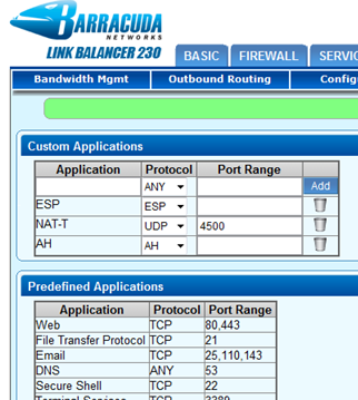
Step 1. Add Missing Applications
IKE, GRE, and PPTP are included in the Predefined Applications by default. Navigate to POLICY > Applications > Custom Applications and create custom applications for ESP, AH, and NAT-T with the following settings:
| Application | Settings |
|---|---|
| ESP |
|
| AH |
|
| NAT-T |
|
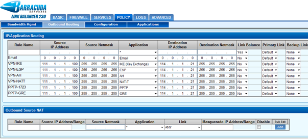
Step 2. Create a New IP / Application Routing Rule
Navigate to POLICY > Outbound Routing > IP/Application Routing and add a new rule with a unique Rule Name. Configure the following condition fields:
| Setting | Description |
|---|---|
| Source IP Address | The IP address (e.g. 111.1.1.100) being NAT’d on the Cisco ASA |
| Source Netmask | The netmask (e.g. 255.255.255.255 if it is a single host, or, if it is a set of IP addresses, the subnet mask must reflect that accordingly). |
| Application | Create rules here for each protocol. |
| Destination IP Address | The IP address of the VPN remote gateway (e.g. 114.1.1.21). |
| Destination Netmask | The netmask (e.g. 255.255.255.255 if it is a single host, or, if it is a set of IP addresses, the subnet mask must reflect that accordingly). |
| Link Balance | Select No and then select a Primary and a Backup link:
|
| NAT | To maintain the original source IP address if there is no backup link, clear this check box. If there is a backup link, select the NAT check box and add Source Network Translation rules to retain the original source IP address(the NAT'd IP address on the firewall behind the Barracuda Link Balancer) for the five applications. |
Configuring the Remote Barracuda Link Balancer (at Michigan)
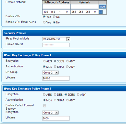
Create a new tunnel at the remote Barracuda Link Balancer (running in firewall-enabled mode) to connect with the Cisco ASA. Make sure that the Security Policies > Phase 1 and Phase 2 settings are identical to the Cisco settings.
The following table provides the reference settings for adding the new VPN tunnel:
| Section | Settings |
|---|---|
| Edit VPN Tunnel |
|
| Security Policies |
|
| IPsec Key Exchange Policy Phase 1 |
|
| IPsec Key Exchange Policy Phase 2 |
|
Verify Whether the Tunnel Works
After the tunnel has been established successfully, a green check mark displays next to it on the VPN page on the Barracuda Link Balancer at both corporate headquarters and Michigan. Both private IP addresses should now be accessible using the ping command.
Troubleshooting
A yellow triangle next to the VPN tunnel on the VPN page of the Barracuda Link Balancer indicates that something does not work as intended.
To troubleshoot:
- Check the LOGS > VPN Log page on the Barracuda Link Balancer.
- You can also refer to the logs generated by the Cisco ASDM web interface.
- Make sure that routing is correctly configured on the client networks and on the Cisco device. Cisco ASDM provides network logs.
- You may also use the TCP Dump command on the ADVANCED > Troubleshooting page on the Barracuda Link Balancer.