

Before proceeding:
- If you are installing an appliance, complete Step 3 - How to Activate and Update the Barracuda Load Balancer ADC.
- If you are installing a virtual system, complete Barracuda Load Balancer ADC Vx Quick Start Guide.
This article applies to both virtual systems and appliances.
Determine Your Deployment
Read Deployment to assist you in deciding how to deploy your network. If you haven't already, make physical connections from the data ports on the Barracuda Load Balancer ADC appliance or from your virtual system's host machine to the relevant switches.
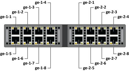
Ports and Interfaces Mapping
In the web UI, the network interfaces that correspond to physical ports are referred to as gt-x-y where:
- g is gigabit
- t is the type of connection (e for Ethernet, f for fiber-optic)
- x is the number of the module of 8 ports, where the left-most module is number 1
- y is the number of the port within the module, where the top left port is number 1
On a Barracuda Load Balancer ADC Vx (virtual system), the network interfaces are numbered in the order you assigned the network interface cards to the virtual system.
Configure Network Interfaces
Earlier, you entered the management IP address (using the administrative console for appliances). Now you should configure your other network interfaces so that you can create services.
Configuring the default gateway for an interface ensures that return traffic exits the Barracuda Load Balancer ADC correctly. If the default gateway is not configured, the outgoing traffic uses the default gateway of the management interface.
In the following examples, ge-1-1 refers to a physical port connected into the network so that it accepts incoming traffic.
Option 1: One-Armed With Separate Management Network
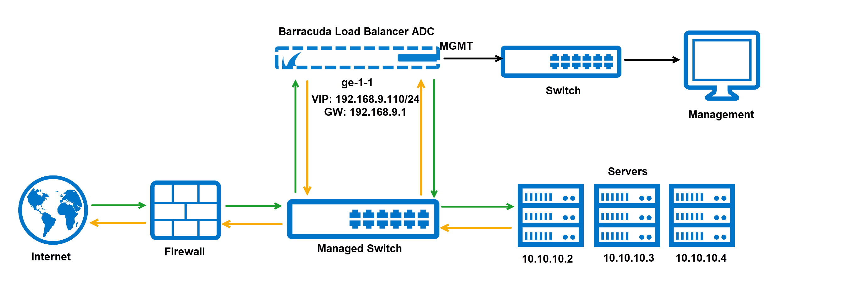
In this case, incoming traffic is on the same subnet as the servers, and the management port is on a separate subnet. ge-1-1 is connected into the network so that it accepts incoming traffic.
- Configure the IP address for ge-1-1 using the NETWORK > Interfaces page.
- Configure the default gateway for ge-1-1 using the NETWORK > Routes page.
If you have both bonded interfaces and VLANs, configure the bonded interfaces first. For each bonded interface:
- Configure bonded ports using the NETWORK > Ports page.
- Configure the IP address for each bonded interface using the NETWORK > Interfaces page.
- Configure the default gateway for each bonded interface using the NETWORK > Routes page.
For each VLAN:
- Configure VLANs using the NETWORK > VLANs page.
- Configure the IP address for each VLAN using the NETWORK > Interfaces page.
- Configure the default gateway for each VLAN using the NETWORK > Routes page.
Option 2: Two-Armed With Separate Management Network
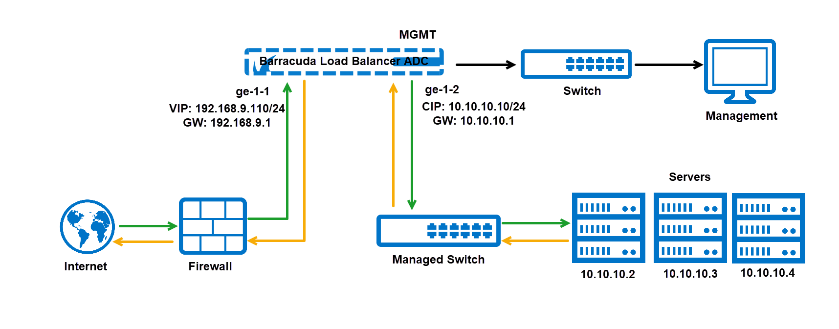
In this environment, i ncoming traffic is on a different subnet from the servers, and the management port is on a separate subnet. ge-1-1 is connected into the network so that it accepts incoming traffic, and ge-1-2 is connected to the servers.
- Configure the IP address for ge-1-1, ge 1-2, etc. using the NETWORK > Interfaces page.
- Configure the default gateway for ge-1-1 using the NETWORK > Routes page. If any other interfaces accept incoming traffic, create default gateways for those interfaces.
If you have both bonded interfaces and VLANs, configure the bonded interfaces first. For each bonded interface:
- Configure bonded ports using the NETWORK > Ports page.
- Configure the IP address for each bonded interface using the NETWORK > Interfaces page.
- Configure the default gateway for each bonded interface using the NETWORK > Routes page.
For each VLAN:
- Configure VLANs using the NETWORK > VLANs page.
- Configure the IP address for each VLAN using the NETWORK > Interfaces page.
- Configure the default gateway for each VLAN using the NETWORK > Routes page.
Option 3: One-Armed Without Separate Management Network
In this case, incoming traffic is on the same subnet as the real servers, and the management port is on that same subnet. Generally, this describes a topology where all systems are on a flat network. No additional gateways need to be defined on the Barracuda Load Balancer ADC. I t is more secure to segregate the production traffic from the management interface, as in Option 1.
- Configure the IP address for ge-1-1 using the NETWORK > Interfaces page.
Configure Services
You are now ready to configure services and real servers.
- On the BASIC > Services page, create each service by identifying a VIP address, port, and associating one or more real servers with it.
If you have a two-armed network, you may need to create a static route for the real servers:
- On the NETWORK > Routes page, create a static route using the Static Routes table.
For more information about services, see Services.