

This article walks you through the steps to configure the Barracuda Load Balancer ADC instances for high availability in the same availability zone in Amazon Web Services.
Step 1. Deploy Two Barracuda Load Balancer ADC Instances on Amazon Web Services
Follow the instructions mentioned in Step 5. Deploy the Barracuda Load Balancer ADC on Amazon Web Services in the Barracuda Load Balancer ADC Deployment and Quick Start Guide for Amazon Web Services article and deploy two Barracuda Load Balancer ADC instances in the same availability zone.
Step 2. Allocate and Assign an Elastic IP Address to Your Instance
Follow the instructions mentioned in Step 6. Allocate and Assign an Elastic IP Address to your Instance in the Barracuda Load Balancer ADC Deployment and Quick Start Guide for Amazon Web Services article to allocate the elastic IP address to the deployed Barracuda Load Balancer ADC instances
Step 3. License the Barracuda Load Balancer ADC
Follow the instructions mentioned in Step 7. (BYOL Only) License the Barracuda Load Balancer ADC in the Barracuda Load Balancer ADC Deployment and Quick Start Guide for Amazon Web Services to provision the deployed Barracuda Load Balancer ADC instances.
Step 4. Verify Your Configuration and Change the Password
Follow the instructions mentioned in Step 8. Verify your Configuration and Change the Password in the Barracuda Load Balancer ADC Deployment and Quick Start Guide for Amazon Web Services article to verify your configuration and change the password on both of the deployed Barracuda Load Balancer ADC instances.
Step 5. Cluster the Deployed Barracuda Load Balancer ADC Instances
Follow the steps below to cluster your Barracuda Load Balancer ADC virtual machines in Amazon Web Services:
- Log into the first Barracuda Load Balancer ADC web interface that will act as your Primary/Active unit. In the instructions below, consider this virtual machine as Barracuda-LB-ADC1.
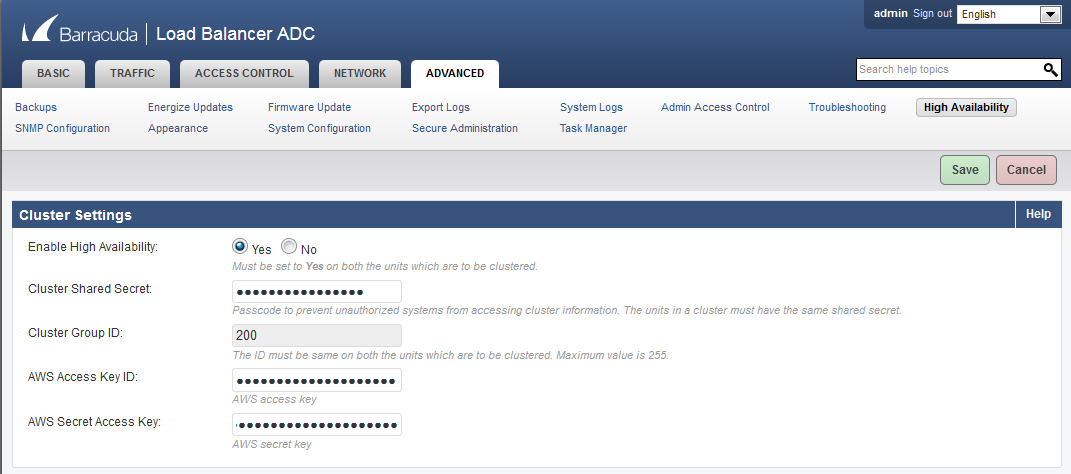
- In the Barracuda-LB-ADC1 web interface, go to the ADVANCED > High Availability page and do the following configuration in the Cluster Settings section:
- Set Enable High Availability to Yes.
- Enter a Cluster Shared Secret password. This is the shared passcode that the clustered units use when communicating with one another. Both systems in the cluster must have the same shared secret.
- Enter the Cluster Group ID. The ID should be the same on both Barracuda Load Balancer ADC instances that are to be clustered. If, on the local network, other network components, such as firewalls, are clustered using VRRP, they should use a different Cluster Group ID than this one. Maximum value is 255.
- AWS Access Key ID: (Optional) Enter the access key ID created in Step 2: (Optional) Get the Access Keys for Your AWS Account.
- AWS Secret Access Key: (Optional) Enter the secret access key created in Step 2: (Optional) Get the Access Keys for Your AWS Account.
- Click Save.
- Log into the second Barracuda Load Balancer ADC web interface that will act as your Secondary/Backup unit. In the instructions below, consider this virtual machine as Barracuda-LB-ADC2.
- In the Barracuda-LB-ADC2 web interface, go to the ADVANCED > High Availability page and do the following configuration:
- Repeat step 2.a to step 2.e in the Cluster Settings section as mentioned in Step 7: Cluster the Deployed Barracuda Load Balancer ADC Instances.
- In the Clustered Systems section, enter the management IP address of the active Barracuda Load Balancer ADC and click Join Cluster.
- The clustering will run as a background task and take a few minutes to complete. Do not do any other configuration changes while the clustering task is running.
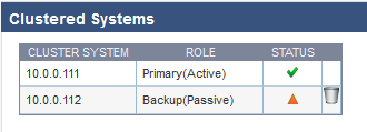
- After a few minutes, refresh the ADVANCED > High Availability page on both systems and verify the following:
- Each system's management IP address appears in the Clustered Systems table.
- The status of the Primary (active) system should be .
- The status of the Backup (passive) system should be .
Continue with Configuring Services on the Barracuda Load Balancer ADC in High Availability Environment.
Step 6. Configure the Service(s) on the Barracuda Load Balancer ADC
This section includes:
- Configuring the Service(s) on the Barracuda Load Balancer ADC Instance with Interfaces of the Same Subnet
- Configuring the Service(s) on the Barracuda Load Balancer ADC Instance with Interfaces from the Multiple Network
Configuring Services on the Barracuda Load Balancer ADC Instance with Interfaces of the Same Subnet.
If you have deployed the Barracuda Load Balancer ADC instance with two interfaces (i.e., mgmt (eth0) and ge-1-1 (eth1)) from the same network, create the service by following the steps mentioned below to reach the instance from the external network:
- Log into the Barracuda-LB-ADC1 (Primary/Active unit) web interface.
- Go to the BASIC > Services page. Use the secondary private IP addresses assigned to the instance as your VIP to create services. See Step.4 (Optional) Assign Multiple Private IP Address(es) to the Network Interface of Instance in the Barracuda Load Balancer ADC Deployment and Quick Start Guide for Amazon Web Services article. For more information on how to add a service, click the Help button in the web interface.
- Go to the NETWORK > Routes page.
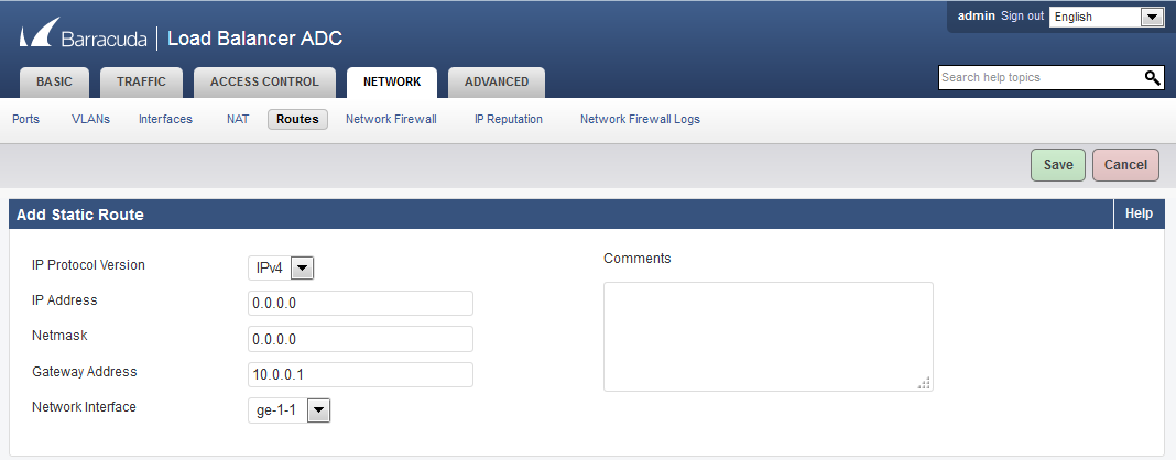
- In the Add Static Route section:
- IP Protocol Version - Select IPv4
- IP Address - Enter 0.0.0.0.
- Netmask - Enter 0.0.0.0.
- Gateway Address - Enter 10.0.0.1.
- Network Interface - Select ge-1-1.
- Click Save.
Configuring Services on the Barracuda Load Balancer ADC with Interfaces from Multiple Networks
If you have deployed the Barracuda Load Balancer ADC instance with three interfaces, where two interfaces (i.e., mgmt (eth0) and ge-1-1 (eth1) are from the same network and the other interface (ge-1-2 (eth2)) is from a different network, you must assign secondary private IP address to each interface and then associate each secondary IP address with an elastic IP address, so that the instance can be accessed from the external network.
Perform the steps below to assign secondary private IP addresses and associate elastic IP address:
Follow step 1 and 2 mentioned in the Configuring Services on the Barracuda Load Balancer ADC Instance with Interfaces of the Same Subnet section.
- Go to the NETWORK > Routes page, and add a static route for ge-1-1 interface as mentioned below:
- IP Protocol Version: Select IPv4
- IP Address: Enter 0.0.0.0.
- Netmask: Enter 0.0.0.0.
- Gateway Address: Enter 10.0.0.1.
- Network Interface: Select ge-1-1.
- Click Save.
- Add a static route for ge-1-2 interface as mentioned below:
- IP Protocol Version: Select IPv4
- IP Address: Enter 0.0.0.0.
- Netmask: Enter 0.0.0.0.
- Gateway Address: Enter 10.0.1.1.
- Network Interface: Select ge-1-2.
- Click Save.
After creating services and adding routes to the Barracuda Load Balancer ADC instance that is deployed with interfaces from multiple networks, you must map the internet gateway in the routing table. See Map the Internet Gateway in the Routing Table.
Map the Internet Gateway in the Routing Table
To transmit traffic through the ge-1-2 interface that is in a different subnet than that of the default public subnet, you should map the subnet to the internet gateway in the routing table, so that the subnet is reachable from the external network. Perform the following steps:
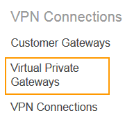
- From the VPC Dashboard, select Virtual Private Gateways under VPN Connections in the left panel.
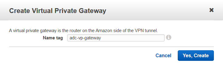
- Click Create Virtual Private Gateway.
- In the Create Virtual Private Gateway window, enter a name for the virtual private gateway in the Name tag field and click Yes, Create.
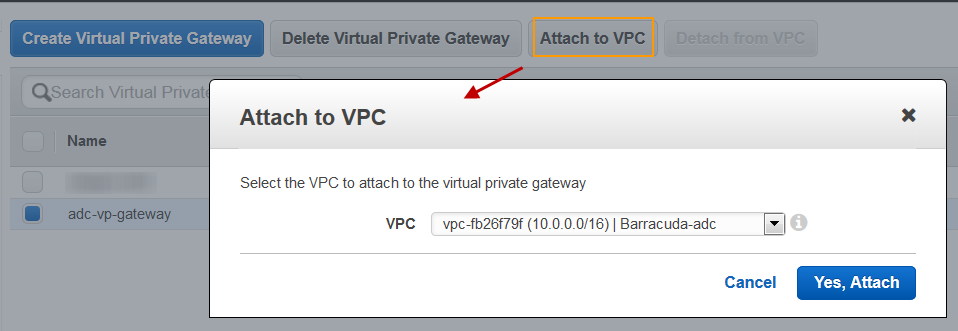
- Select the created virtual private gateway from the list, and click Attach to VPC.
- In the Attach to VPC window, select the VPC to which you want to attach the virtual private gateway from the VPC list, and click Yes, Attach.
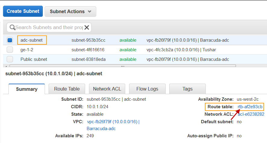
- Select Subnets under Virtual Private in the left panel.
- Select the subnet that is used for creating the ge-1-2 interface from the subnets list. Note the Route table entry under Summary.
- Select Route Tables under Virtual Private Cloud in the left panel.
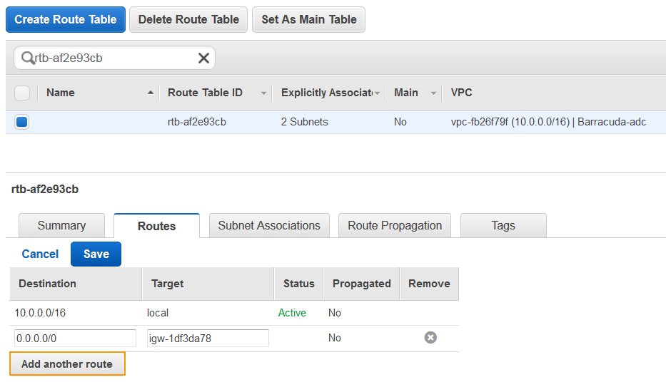
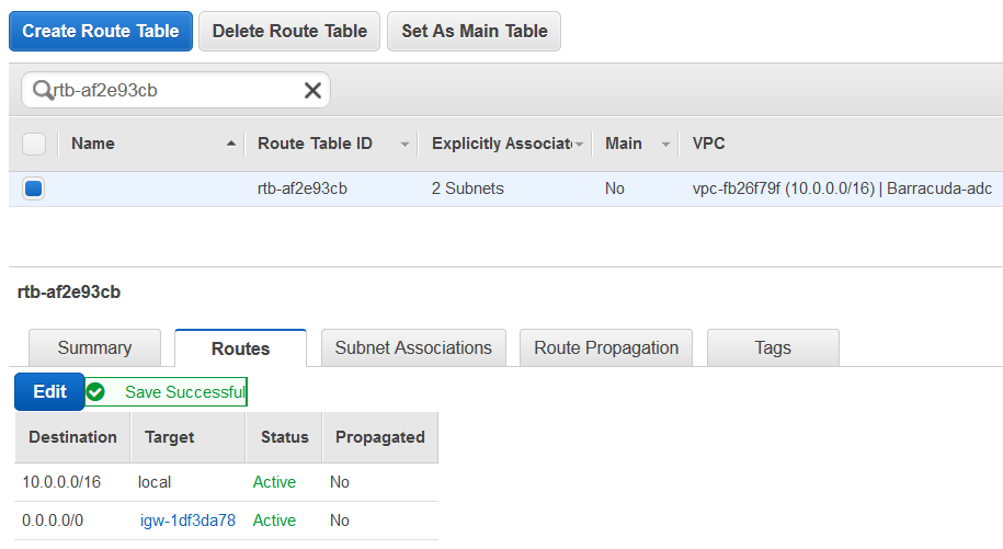
- Select the route you noted in step 7, click on the Routes tab and click Edit.
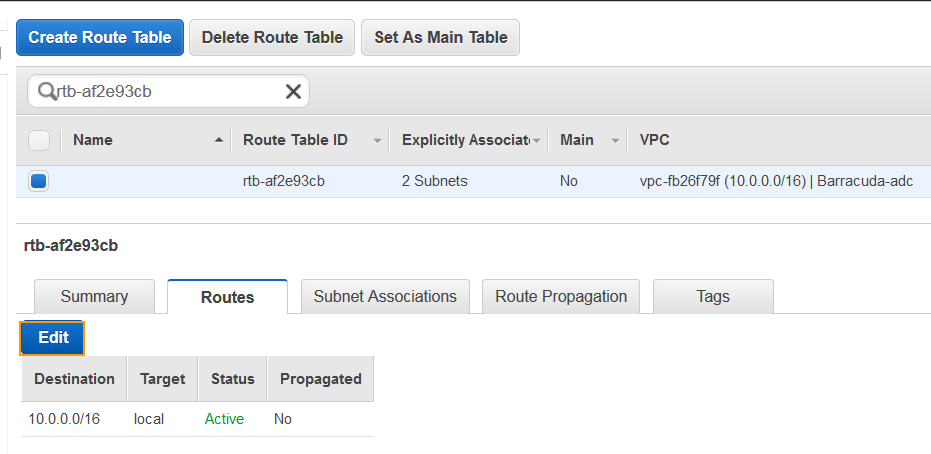
- Click Add another route with Destination as 0.0.0.0 and Target as “igw-1df3da78”, which is the internet gateway. Click Save.
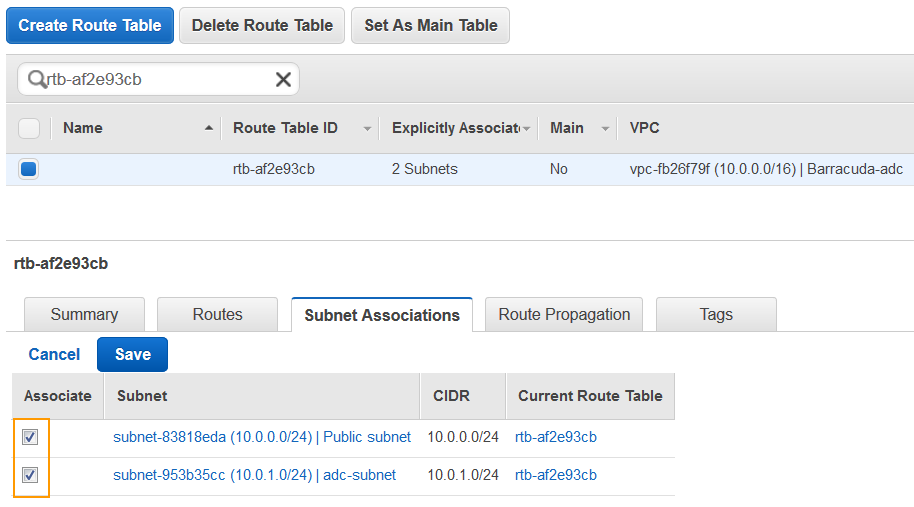
- Select the Subnet Associations tab, and click Edit.
- Ensure the Associate check box is selected for both the subnets, and click Save.
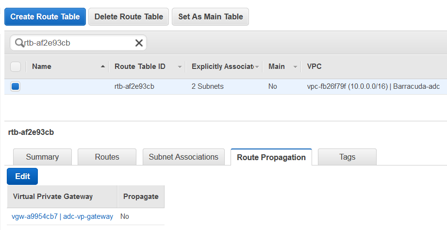
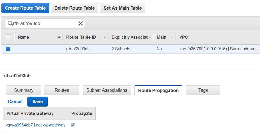
- Select the Route Propagation tab, click Edit, and select the Propagate check box next to virtual private gateway. Click Save.
Now, you can access the service from the external network using the elastic IP address assigned to the service virtual IP addresses.