This article provides migration instructions for WSG inline bridge setups in SecureEdge.
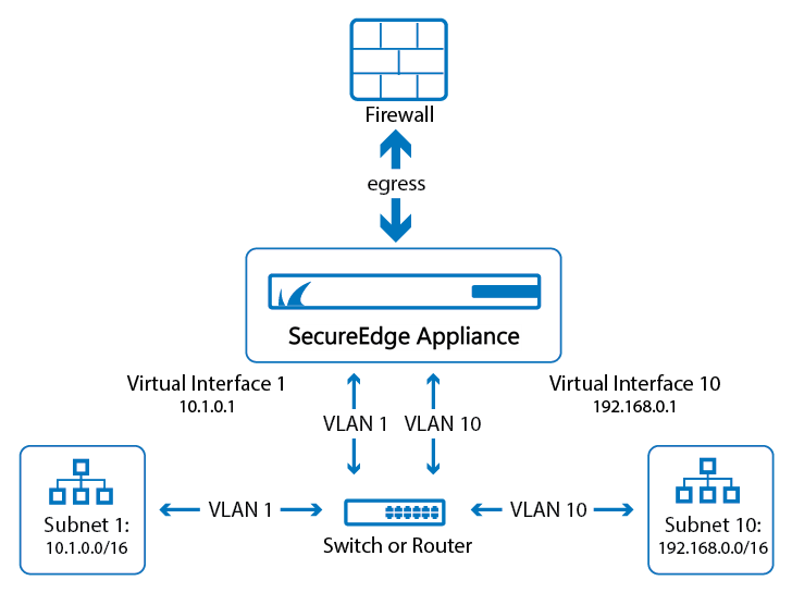
LAN-VLAN Deployment
The figure below illustrates a LAN-VLAN setup using an inline bridge deployment.
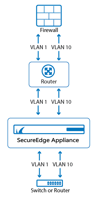
Bridge VLAN Deployment
The figure below illustrates a Bridge-VLAN setup using an inline bridge deployment.
Setups are similar to the above but need configuration changes.
Note: Assuming the border firewall connects on port P2 and the local LAN switch on port P3, set up each VLAN using an individual bridge-type WAN device. For example, in this case, a VLAN 10 configuration with gateway 192.168.10.1 and the Site device reachable via 192.168.10.10 .
Initial Setup
LAN-VLAN Deployment
Add the appliance to your SecureEdge Manager account as a Site device.
Go to https://se.barracudanetworks.com and log in with your existing Barracuda Cloud Control account.
The chosen Tenant/Workspace is displayed in the top menu bar.
From the drop-down menu, select the workspace your appliance should be assigned to.
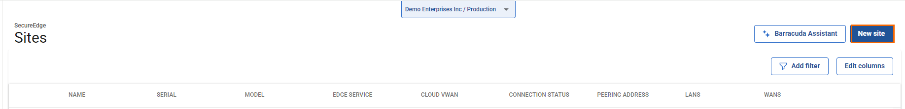
Go to Infrastructure > Sites.
The Sites page opens. In the top-right corner of the window, click New site. For more information, see How to Create an Inline Bridge on a Stand-Alone Site.
The New Site Basic Information blade opens. Enter values for the following:
Name – Enter the name of the site.
Edge Service – Select (None).
Root Password – Enter the root password.
Confirm Root Password – Retype the root password to confirm.
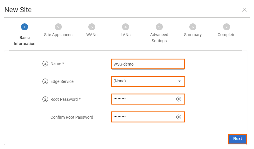
Click Next. The Site Appliances blade opens.
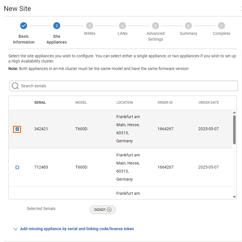
Note: If your appliance is not listed, you can add it by using the serial number and the linking code found on the back of the Quick Start Guide delivered with your appliance.
Select your appliance from the list of appliances linked to your account. For a high availability cluster, select two appliances. For more information on high availability, see High Availability. Note: After ordering, it might take up to 3 hours before your device is listed.
Click Add missing site appliance by serial and linking code/license token.
Specify values for the following:
Serial – Enter the serial number of your appliance.
Code/Token – Enter the linking code (located on the back of the Quick Start Guide shipped with your hardware appliance), or the token of your VTx appliance.
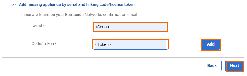
Click Add to add the device to your account.
Click Next. The WANs blade opens.
Select the number of desired WAN connections from the drop-down list.
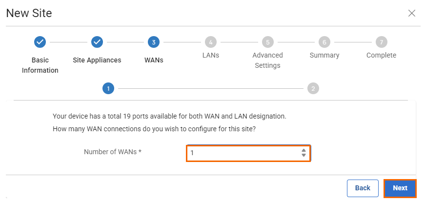
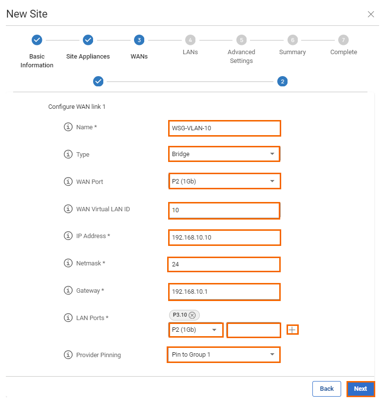
Click Next. The Configure WAN link blade opens.
Specify values for the following:
Name – Enter a unique name for the WAN link. For example, in this case,
WSG-VLAN-10Type – Select Bridge from the drop-down list.
WAN Port – Select P2.
WAN Virtual LAN ID – Enter
10.IP Address – Enter the network IP address assigned to the port. For example, in this case,
192.168.10.10Netmask – Enter the CIDR netmask suffix. E.g.,
24Gateway – Enter the gateway IP address. For example, in this case,
192.168.10.1LAN Ports – Select the LAN ports this interface is connected to and click +. For example, in this case, the selected LAN port is
P3.10Provider Pinning – Select a provider classification from the drop-down list.
Click Next. The LANs blade opens.
Select the number of desired LAN connections from the drop-down list.
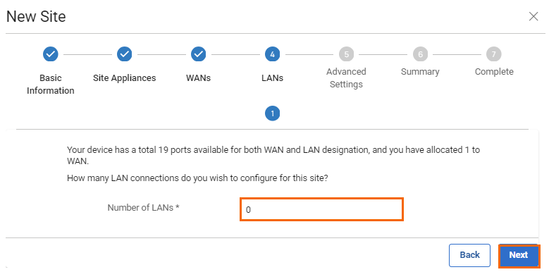
Click Next. The Advanced Settings blade opens.
Specify values for the following:
Update Window Timezone – Select Dynamic from the drop-down list, or select the time zone where the box is located.
Primary DNS – Enter the IP address of the primary DNS server.
Secondary DNS – Enter the IP address of the secondary DNS server.
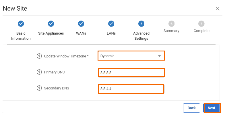
Click Next. The Summary blade opens.
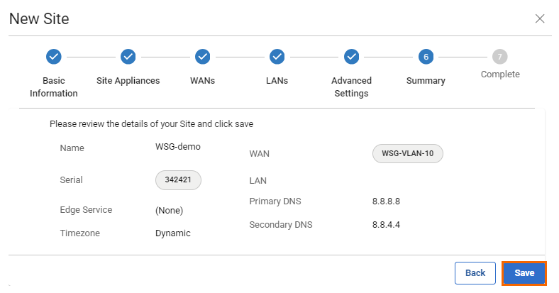
Review your specifications. If everything is correct, click Save.
After your site configuration has been created successfully, click Finish.
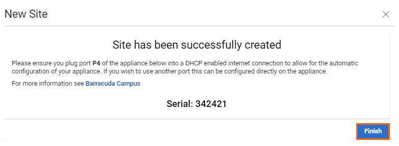
The appliance will automatically apply the configuration upon its first boot.
Bridge VLAN Deployment
Follow the initial setup, except for the WAN interface configuration.
Configure the WAN interface as shown below:
Name – Enter a unique name for the WAN link. For example, in this case,
WSG-VLAN-1Type – Select Bridge from the drop-down list.
WAN Port – Select P2.
WAN Virtual LAN ID – Enter
1.IP Address – Enter the network IP address assigned to the port. For example, in this case,
192.168.10.10Netmask – Enter the CIDR netmask suffix. E.g.,
24Gateway – Enter the gateway IP address. For example, in this case,
192.168.10.1LAN Ports – Select the LAN ports this interface is connected to and click +. For example, in this case, the selected LAN port is
P3.1Provider Pinning – Select a provider classification from the drop-down list.

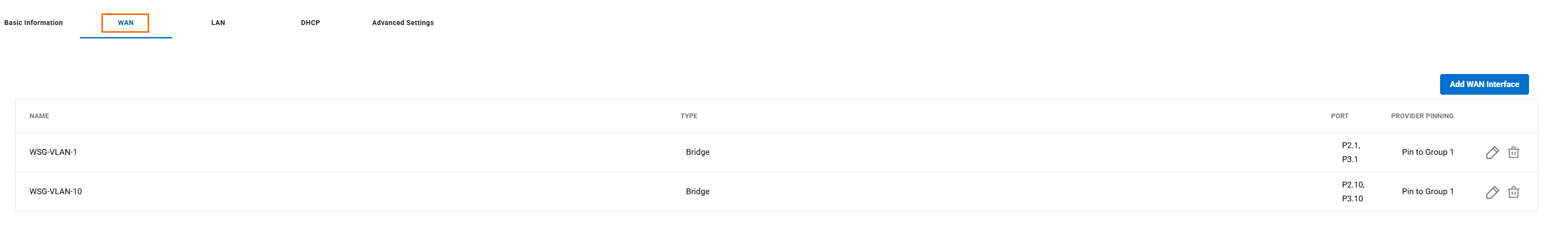
After saving the configuration for both VLANs and setting up one WAN bridge interface each, the bridge's network details will appear in the WANS table on the Sites page.