

System hardware features include front and back panel controls, ports and LED indicators on the Barracuda Web Application Firewall.
Front Panel Features of Model 360 / 460 (Old Hardware)
The following figure shows the front panel components of Model 360 and 460 described in Table 1.
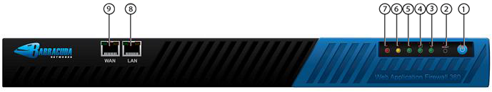
Table 1
Diagram Location | Description |
|---|---|
1 | On/Off button |
2 | Reset button |
3 | Power Indicator |
4 | Disk Activity |
5 | Management Network Activity |
6 | Indicates System Bypass Mode |
7 | Indicates a Failed Status of the System |
8 | LAN Port |
9 | WAN Port |
Back Panel Features of Model 360 / 460 (Old Hardware)
The following figure shows the back panel components described in Table 2 .
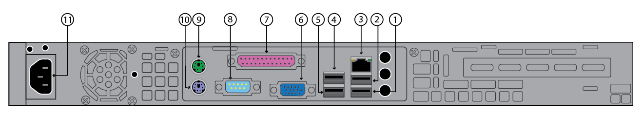
Table 2
Diagram Location | Description |
|---|---|
1 | Unused USB Port |
2 | Unused USB Port |
3 | Unused Network Port |
4 | Unused USB Port |
5 | Unused USB Port |
6 | VGA Display (console) |
7 | Unused Printer Port |
8 | Serial Port |
9 | Mouse |
10 | Keyboard |
11 | Power Supply |
If your system was shipped during or after January 2013, the Front Panel is as follows:

The components are described in Table 3 .
Table 3
Diagram Location | Description |
|---|---|
1 | Disk Activity |
2 | Power Indicator |
3 | Reset button |
4 | On/Off button |
5 | LAN Port |
6 | WAN Port |
The Back Panel is as follows:
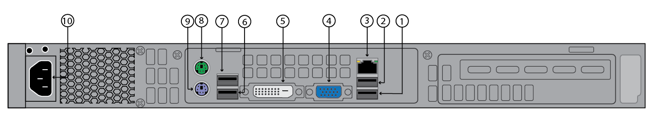
The components are described in Table 4.
Table 4
Diagram Location | Description |
|---|---|
1 | Unused USB Port |
2 | Unused USB Port |
3 | Management Port |
4 | VGA Display (console) |
5 | DVI Port |
6 | Unused USB Port |
7 | Unused USB Port |
8 | Mouse |
9 | Keyboard |
10 | Power Supply |
Front Panel Features of Model 360/460 (New Hardware)
The components are described in Table 5.
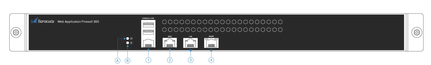
Table 5
Diagram Location | Description |
|---|---|
A | Disk Activity |
B | Power Indicator |
1 | Console and USB Ports |
2 | WAN Port |
3 | LAN Port |
4 | MGMT Port |
Back Panel 360/460 (New Hardware)
The components are described in Table 6.
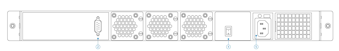
Table 6
Diagram Location | Description |
|---|---|
2 | VGA Port |
4 | On/Off Button |
5 | Power Supply |
Front Panel Features of Model 660
The following figure shows the front panel components described in Table 7.
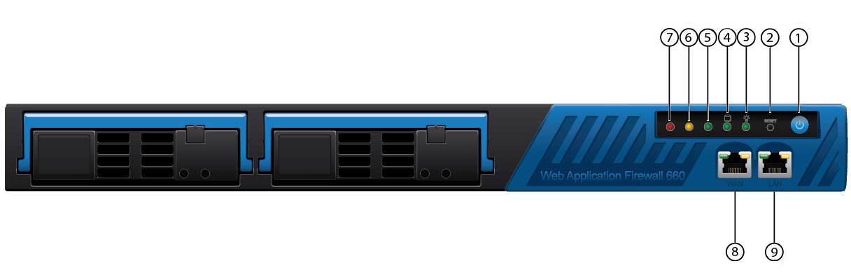
Table 7
Diagram Location | Description |
|---|---|
1 | On/Off button |
2 | Reset button |
3 | Power Indicator |
4 | Disk Activity |
5 | Unused LED |
6 | Indicates System Bypass Mode |
7 | Indicates a Failed Status of the System |
8 | WAN Port |
9 | LAN Port |
Back Panel Features of Model 660
The following figure shows the back panel components described in Table 8.
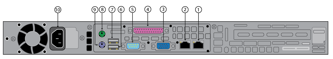
Table 8
Diagram Location | Description |
|---|---|
1 | Management Port 1 |
2 | Management Port 2 |
3 | VGA Display (console) |
4 | Unused Printer Port |
5 | Serial Port |
6 | Unused USB Port |
7 | Unused USB Port |
8 | Mouse |
9 | Keyboard |
10 | Power Supply |
If your system was shipped during or after March 2023, the Front Panel is as follows:
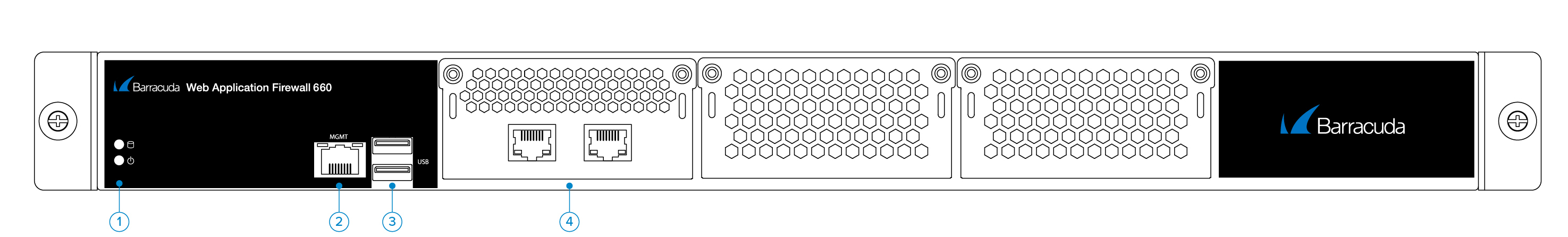
The components are described in Table 9.
Table 9
Diagram Location | Description |
|---|---|
1 | On/Off button |
2 | Management Port |
3 | USB Port |
4 | Traffic Ports |
The Back Panel is as follows:
The components are described in Table 10.
Table 10
Diagram Location | Description |
|---|---|
1 | USB Port |
2 | VGA Port |
3 | Fan |
4 | On/Off button |
5 | Power Supply |
Front Panel Features of Model 86x and 96x
The following figure shows the front panel of the Model 860 described in Table 11:
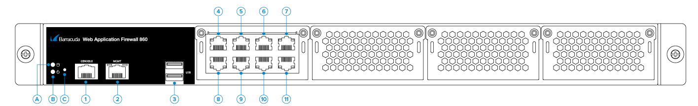
Table 11
Diagram Location | Description |
|---|---|
A | HDD LED |
B | PWR LED |
C | Reset |
1 | Console |
2 | MGMT |
3 | USB |
4 | Port 0: 1Gbps |
5 | Port 1: 1Gbps |
6 | Port 2: 1Gbps |
7 | Port 3: 1Gbps |
8 | Port 4: 1Gbps |
9 | Port 5: 1Gbps |
10 | Port 6: 1Gbps |
11 | Port 7: 1Gbps |
The following figure shows the front panel of the Model 861 described in Table 12 :
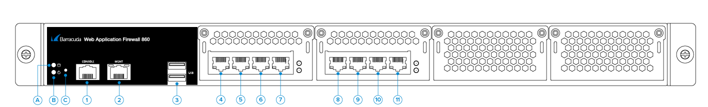
Table 12
Diagram Location | Description |
|---|---|
A | HDD LED |
B | PWR LED |
C | Reset |
1 | Console |
2 | MGMT |
3 | USB |
4 | Port 0: 1Gbps |
5 | Port 1: 1Gbps |
6 | Port 2: 1Gbps |
7 | Port 3: 1Gbps |
8 | Port 4: 1Gbps |
9 | Port 5: 1Gbps |
10 | Port 6: 1Gbps |
11 | Port 7: 1Gbps |
The following figure shows the front panel of the Model 862 described in Table 13 :
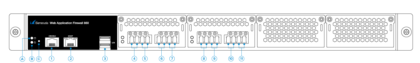
Table 13
Diagram Location | Description |
|---|---|
A | HDD LED |
B | PWR LED |
C | Reset |
1 | Console |
2 | MGMT |
3 | USB |
4 | Port 0: 1Gbps |
5 | Port 1: 1Gbps |
6 | Port 2: 1Gbps |
7 | Port 3: 1Gbps |
8 | Port 4: 1Gbps |
9 | Port 5: 1Gbps |
10 | Port 6: 1Gbps |
11 | Port 7: 1Gbps |
The following figure shows the front panel of the Model 960 described in Table 14:
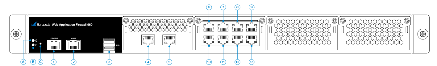
Table 14
Diagram Location | Description |
|---|---|
A | HDD LED |
B | PWR LED |
C | Reset |
1 | Console |
2 | MGMT |
3 | USB |
4 | Port 0: 10 Gbps |
5 | Port 1: 10 Gbps |
6 | Port 2: 1Gbps |
7 | Port 3: 1Gbps |
8 | Port 4: 1Gbps |
9 | Port 5: 1Gbps |
10 | Port 6: 1Gbps |
11 | Port 7: 1Gbps |
12 | Port 8: 1Gbps |
13 | Port 9: 1Gbps |
The following figure shows the front panel of the Model 961 described in Table 15 :
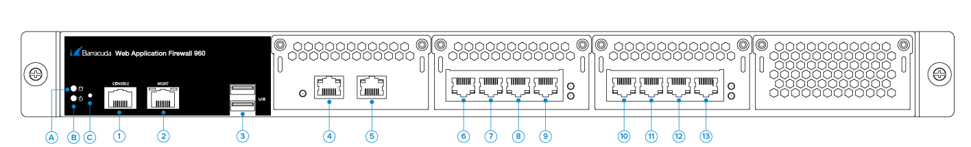
Table 15
Diagram Location | Description |
|---|---|
A | HDD LED |
B | PWR LED |
C | Reset |
1 | Console |
2 | MGMT |
3 | USB |
4 | Port 0: 10 Gbps |
5 | Port 1: 10 Gbps |
6 | Port 2: 1Gbps |
7 | Port 3: 1Gbps |
8 | Port 4: 1Gbps |
9 | Port 5: 1Gbps |
10 | Port 6: 1Gbps |
11 | Port 7: 1Gbps |
12 | Port 8: 1Gbps |
13 | Port 9: 1Gbps |
The following figure shows the front panel of the Model 964 described in Table 16 :
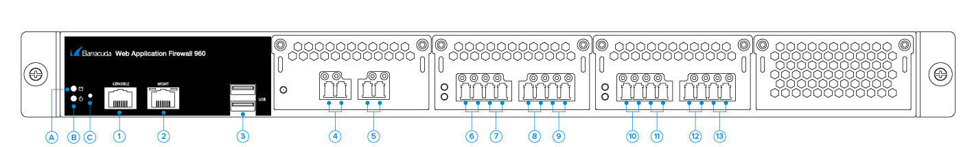
Table 16
Diagram Location | Description |
|---|---|
A | HDD LED |
B | PWR LED |
C | Reset |
1 | Console |
2 | MGMT |
3 | USB |
4 | Port 0: 10 Gbps |
5 | Port 1: 10 Gbps |
6 | Port 2: 1Gbps |
7 | Port 3: 1Gbps |
8 | Port 4: 1Gbps |
9 | Port 5: 1Gbps |
10 | Port 6: 1Gbps |
11 | Port 7: 1Gbps |
12 | Port 8: 1Gbps |
13 | Port 9: 1Gbps |
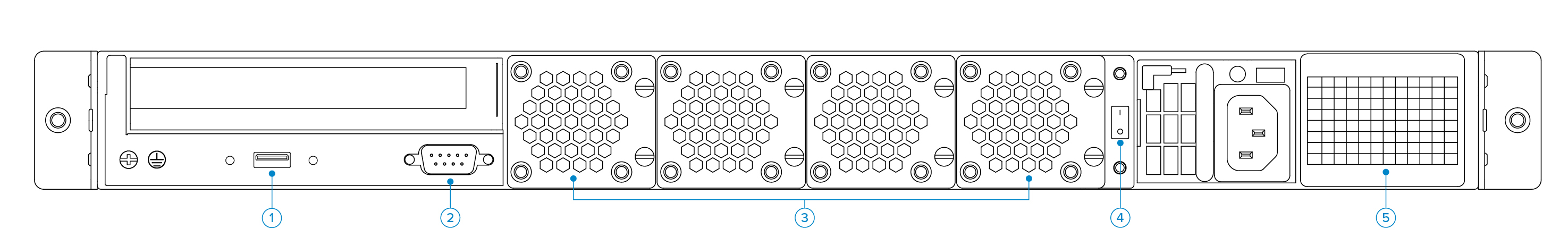
Back Panel Features of Model 86x and 96x
The following figure shows the back panel components of Model 86x and 96x described in Table 17.
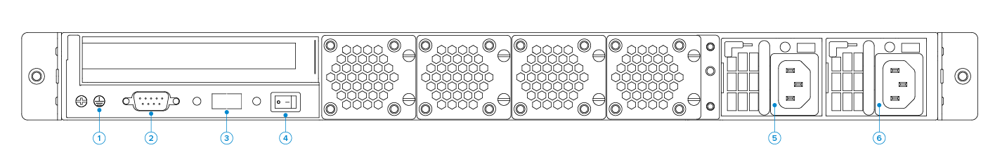
Table 17
Diagram Location | Description |
|---|---|
1 | GND |
2 | VGA |
3 | USB |
4 | PWR SW |
Front Panel Features of Model 1060b
The following figure shows the front panel components of Model 1060b described in Table 18.
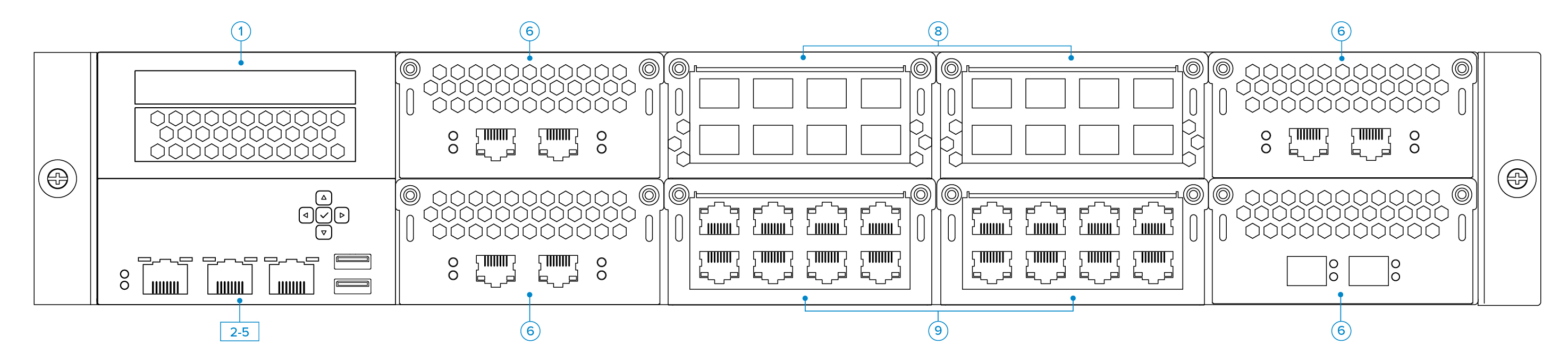
Table 18
Diagram Location | Description |
|---|---|
1 | LED Panel |
2-5 | Console, MGMT and IPMI Ports, |
6 | SFP Ports |
8 | Traffic Ports |
9 | Traffic Ports |
Back Panel Features of Model 1060b
The following figure shows the back panel components described in Table 19.
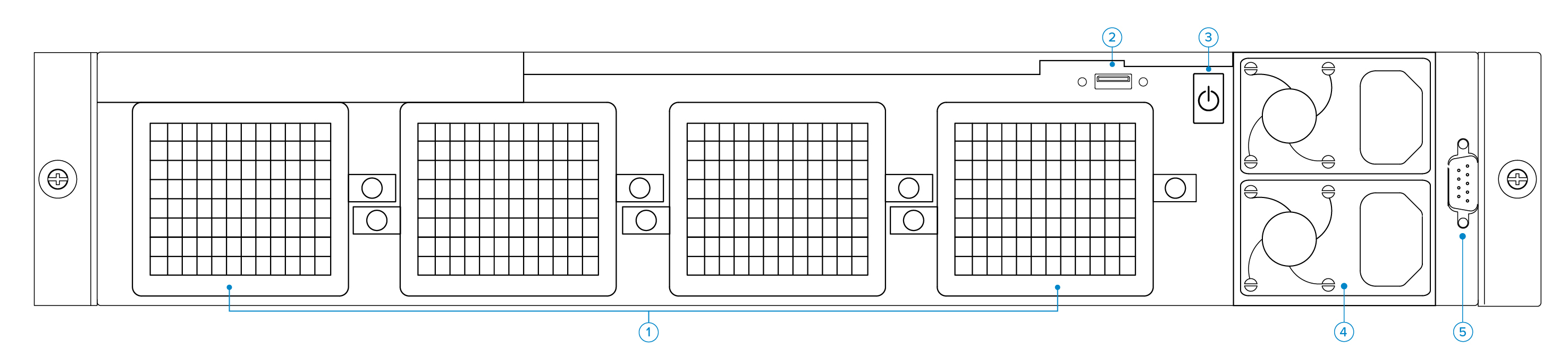
Table 19
Diagram Location | Description |
|---|---|
1 | Fan |
2 | USB Port |
3 | On/Off button |
4 | Power Suppy |
5 | VGA Port |
Hardware Compliance
This section contains compliance information for the Barracuda Web Application Firewall hardware.
Notice for the USA
Compliance Information Statement (Declaration of Conformity Procedure) DoC FCC Part 15: This device complies with part 15 of the FCC Rules.
Operation is subject to the following conditions:
This device may not cause harmful interference, and
This device must accept any interference received including interference that may cause undesired operation. If this equipment does cause harmful interference to radio or television reception, which can be determined by turning the equipment off and on, the user in encouraged to try one or more of the following measures:
Reorient or relocate the receiving antenna.
Increase the separation between the equipment and the receiver.
Plug the equipment into an outlet on a circuit different from that of the receiver.
Consult the dealer on an experienced radio/ television technician for help.
Notice for Canada
This apparatus compiles with the Class B limits for radio interference as specified in the Canadian Department of Communication Radio Interference Regulations.
Notice for Europe (CE Mark)
This product is in conformity with the Council Directive 89/336/EEC, 92/31/EEC (EMC).