- Model 210
- Model 310 and 410
- Model 610
- Model 610b
- Model 810 front panel
- Model 810 rear panel (2023)
- 810B42023
- Model 910 front panel
- Model 910 rear panel
- Model 1010/1011 front panel
- Model 1010 rear panel (legacy)
- Model 1010 rear panel (2023)
- Model 1011 rear panel (legacy)
- Model 1011 rear panel (2023)
Barracuda Web Security Gateway 210
Barracuda Web Security Gateway 210 Front Panel
The following figure illustrates the Barracuda Web Security Gateway 210 power and disk activity indicator lights.
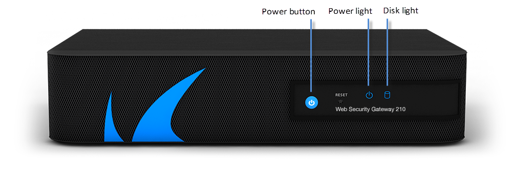
The following table describes the Barracuda Web Security Gateway 210 front panel power and disk activity indicator lights.
| Component Name | Description |
|---|---|
| Power Button | Powers the Barracuda Web Security Gateway on or off |
| Reset Button | Resets the Barracuda Web Security Gateway |
| Power Light | Displays solid blue when the power is on. |
| Disk Light | Displays hard disk activity |
Barracuda Web Security Gateway 210 Rear Panel
The following image illustrates the Barracuda Web Security Gateway 210 rear panel ports and connectors.
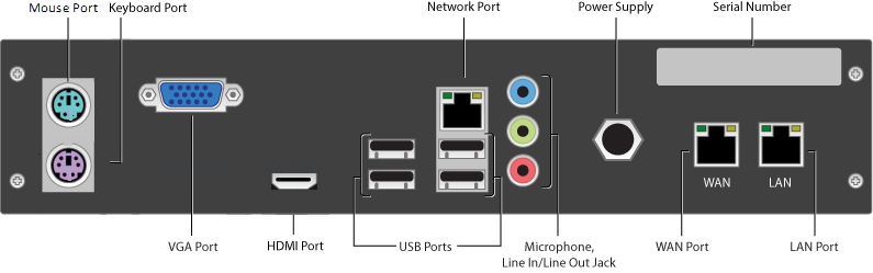
The following table describes the Barracuda Web Security Gateway 210 rear panel ports and connectors.
| Port/Connector Name | Description |
|---|---|
| Mouse Port | Optional. PS2 mouse connection |
| Keyboard Port | Optional . PS2 keyboard connection |
| VGA Port | Recommended . Video graphics array (VGA) monitor connection |
| HDMI Port | Optional. HDMI video connection. |
| USB Ports (4) | Optional. USB device connection |
| Network Port | Network Port |
| Microphone | Optional. Microphone line-in connection |
| Line In/Line Out Jack | Optional. Audio input/output connections |
| Power Supply | Power supply input |
| Serial Number | Appliance serial number |
| WAN/LAN Ports | WAN/LAN ports |
Barracuda Web Security Gateway 310 and 410
Barracuda Web Security Gateway 310 and 410 Front Panel
The following figure illustrates the Barracuda Web Security Gateway 310 and 410 power and disk activity indicator lights.
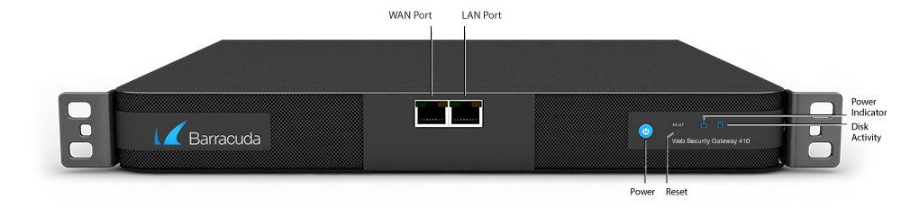
The following table describes the Barracuda Web Security Gateway 310 and 410 power and disk activity indicator lights.
| Component Name | Description |
|---|---|
| WAN port | Port for WAN Connection |
| LAN port | Port for LAN Connection |
| Power Button | Powers the Barracuda Web Security Gateway on or off |
| Reset Button | Resets the Barracuda Web Security Gateway |
| Power Light | Displays a solid blue when the system is powered on |
| Disk Activity | Blinks when the Barracuda Web Security Gateway processes traffic |
Barracuda Web Security Gateway 310 and 410 Rear Panel
The following image illustrates the Barracuda Web Security Gateway 310 and 410 rear panel ports and connectors.
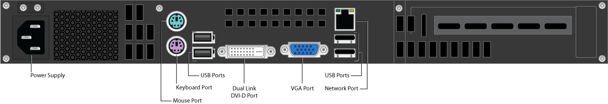
The following table describes the Barracuda Web Security Gateway 310 and 410 rear panel ports and connectors.
| Component Name | Description |
|---|---|
| Power Supply | Connection for the AC power cord, standard |
| Mouse port | PS2 mouse connection |
| Keyboard port | PS2 keyboard connection |
| USB ports (4) | Connection for USB devices |
| Dual Link DVI-D Port | Optional . Digital monitor connection |
| VGA Port | Recommended . Video graphics array (VGA) monitor connection. |
| Network Port | Auxiliary port |
Barracuda Web Security Gateway 610
Barracuda Web Security Gateway 610 Front Panel
The following figure illustrates the Barracuda Web Security Gateway 610 WAN/LAN ports and the disk activity and power indicator lights.
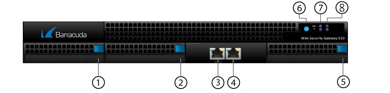
The following table describes the Barracuda Web Security Gateway 610 front panel:
| Diagram Location | Component Name | Description |
|---|---|---|
| 1 | Hard Disk Drive | Location of disk drive |
| 2 | Hard Disk Drive | Location of disk drive |
| 3 | WAN Port | Port for WAN connection |
| 4 | LAN Port | Port for LAN connection |
| 5 | Hard Disk Drive | Location of disk drive |
| 6 | Power Button | Powers the Barracuda Web Security Gateway on or off |
| 7 | Power Light | Displays a solid blue when the system is powered on |
| 8 | Disk Activity | Blinks when the Barracuda Web Security Gateway processes traffic |
Barracuda Web Security Gateway 610 Rear Panel
The following image illustrates the Barracuda Web Security Gateway 610 rear panel ports and connectors.
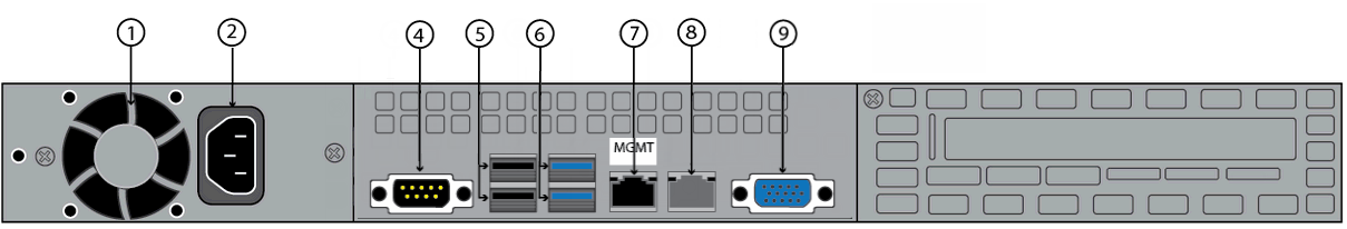
The following table describes the Barracuda Web Security Gateway 610 rear panel ports and connectors.
| Diagram Location | Component Name | Description |
|---|---|---|
| 1 | Fan | Location of the fan |
| 2 | Power supply | Connection for the AC power cord, standard power supply |
| 4 | Serial port | Connection for the serial console cable |
| 5 | USB ports (2, 2.0) | Connection for USB 2.0 devices |
| 6 | USB ports (2, 3.0) | Connection for USB 3.0 devices |
| 7 | Auxiliary port | Web interface management |
| 8 | Not used | Not used |
| 9 | Monitor port | Connection for the monitor |
Barracuda Web Security Gateway 610b
Barracuda Web Security Gateway 610b Front Panel
The following figure illustrates the Barracuda Web Security Gateway 610b Mgmt, USB, WAN/LAN ports and the disk activity and power indicator lights.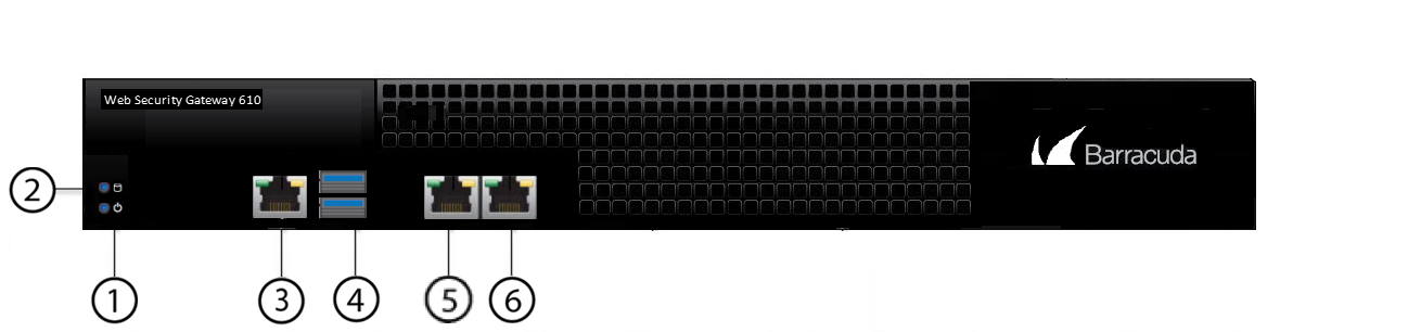
The following table describes the Barracuda Web Security Gateway 610b front panel:
| Diagram Location | Component Name | Description |
|---|---|---|
| 1 | Power Light | Displays a solid blue when the system is powered on |
| 2 | Disk Activity | Blinks when the Barracuda Web Security Gateway processes traffic |
| 3 | Mgmt | Web interface management |
| 4 | USB ports | Connection for USB 3.0 devices |
| 5 | WAN port | 10G NIC for WAN/LAN connection, copper. |
| 6 | LAN port | 1 0G NIC for WAN/LAN connection, copper. |
Barracuda Web Security Gateway 610b Rear Panel
The following image illustrates the Barracuda Web Security Gateway 610b rear panel ports and connectors.
The following table describes the Barracuda Web Security Gateway 610b rear panel ports and connectors.
| Diagram Location | Component Name | Description |
|---|---|---|
| 1 | USB port (3.0) | Connection for USB 3.0 devices |
| 2 | Monitor port | Connection for the monitor |
| 3 | Power switch | Powers the Barracuda Web Security Gateway on or off |
| 4 | Power supply | Connection for the AC power cord, standard power supply |
Barracuda Web Security Gateway 810
Barracuda Web Security Gateway 810 Front Panel
The following figure illustrates the Barracuda Web Security Gateway 810 power and disk (RAID) activity indicator lights.
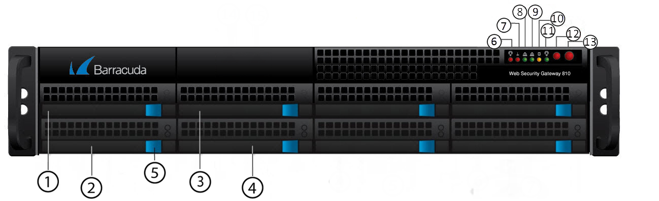
The following table describes the Barracuda Web Security Gateway 810 power and disk activity indicator lights.
| Diagram Location | Component Name | Description |
|---|---|---|
| 1 | Hard Disk Drive | Location of disk drive |
| 2 | Hard Disk Drive | Location of disk drive |
| 3 | Hard Disk Drive | Location of disk drive |
| 4 | Hard Disk Drive | Location of disk drive |
| 5 | Hard Disk Drive Locks | Each drive has a lock/release button |
| 6 | Power failure  | Indicates power supply failure |
| 7 | In older units: Temperature/fan failure | Indicates overheating / fan failure; most likelythe power supply fan. A loose connection could trigger the warning light. Try shutting down and reseating both power supply units. If that does not resolve the issue, request a new power supply. |
7 8 9 10 11 | In newer units: Information LED | 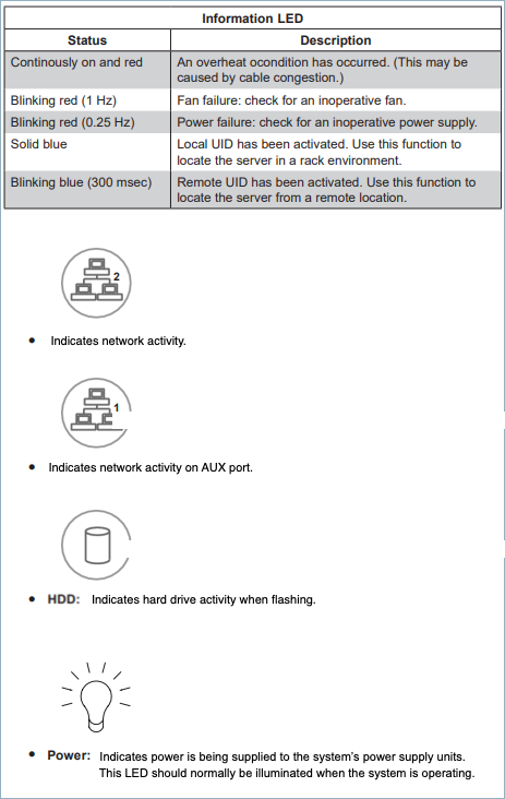 |
| 12 | Reset button | Resets the Barracuda Web Security Gateway |
| 13 | Power button | Powers the Barracuda Web Security Gateway on or off |
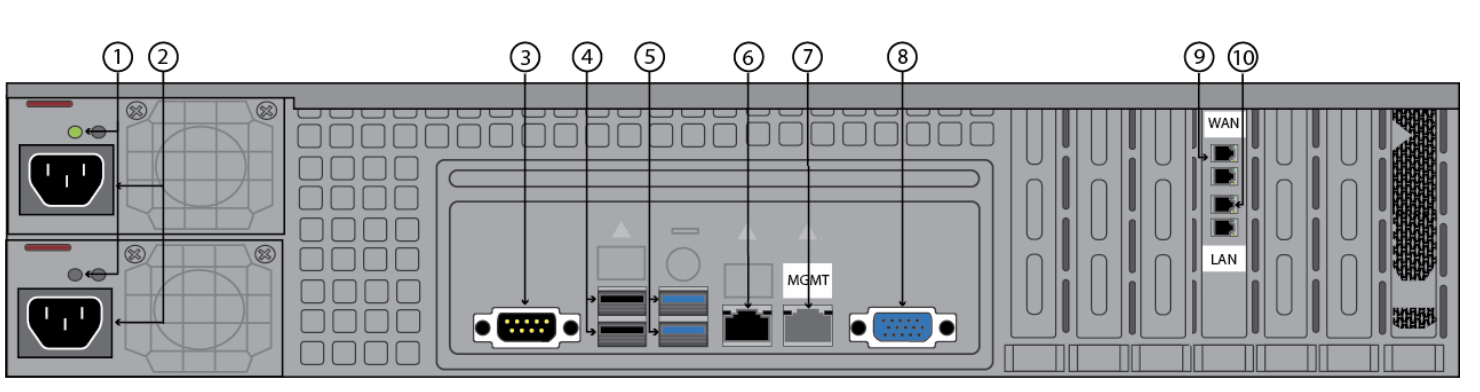
Barracuda Web Security Gateway 810 Rear Panel (Updated as of January 1, 2023)
The following image illustrates the Barracuda Web Security Gateway 810 rear panel ports and connectors. NOTE: This refreshed 810 hardware, available starting from January, 2023, provides 10Gbps throughput and port bonding is no longer available. For the legacy 810 rear panel configuration, see below.
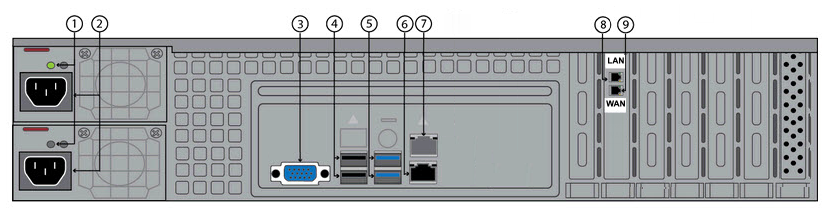
The following table describes the Barracuda Web Security Gateway 810 rear panel ports and connectors.
| Diagram Location | Component Name | Description |
|---|---|---|
| 1 | Power Lights | Displays:
|
| 2 | Hot Swappable Power Supplies (2) | Connection for the AC power cord, standard power supply |
| 3 | Monitor Port | Connection for the monitor |
| 4 | USB ports (2, 2.0) | Connection for USB 2.0 devices |
| 5 | USB ports (2, 3.0) | Connection for USB 3.0 devices |
| 6 | Auxiliary Port | Web interface management |
| 7 | Not used | Not used |
| 8 | LAN Port | 10G NIC for LAN connection, copper |
| 9 | WAN Port | 10G NIC for WAN connection, copper |
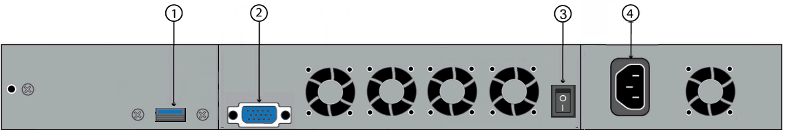
Barracuda Web Security Gateway 810 Rear Panel (deprecated January 1, 2023, and replaced with the above configuration)
The following image illustrates the Barracuda Web Security Gateway 810 rear panel ports and connectors for units manufactured before January 1, 2023. The pairs of WAN and LAN ports are bonded together to provide up to 2GB of traffic throughput; if it is connected to a switch that uses the Spanning-Tree Protocol (STP), and you must configure the switch to disable STP packets on the port channel connected to the Barracuda Web Security Gateway.
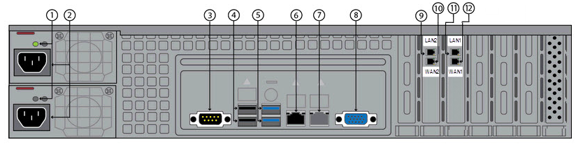
The following table describes the Barracuda Web Security Gateway 810 rear panel ports and connectors for units manufactured before January 1, 2023.
Diagram Location | Component Name | Description |
|---|---|---|
| 1 | Power Lights | Displays:
|
| 2 | Hot Swappable Power Supplies (2) | Connection for the AC power cord, standard power supply |
| 3 | Serial Port | Not used |
| 4 | USB ports (2, 2.0) | Connection for USB 2.0 devices |
| 5 | USB ports (2, 3.0) | Connection for USB 3.0 devices |
| 6 | Auxiliary Port | Web interface management |
| 7 | Not used | Not used |
| 8 | Monitor Port | Connection for the monitor |
| 9 | LAN2 Port | 1G NIC for LAN connection, copper |
| 10 | WAN2 Port | 1G NIC for WAN connection, copper |
| 11 | LAN1 Port | 1G NIC for LAN connection, copper |
| 12 | WAN1 Port | 1G NIC for WAN connection, copper |
Barracuda Web Security Gateway 910
Barracuda Web Security Gateway 910 Front Panel
The following figure illustrates the Barracuda Web Security Gateway 910 power and disk (RAID) activity indicator lights.
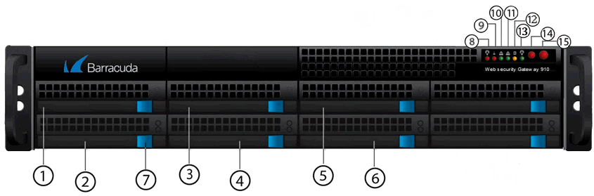
| Diagram Location | Component Name | Description |
|---|---|---|
| 1 | Hard Disk Drive | Location of disk drive |
| 2 | Hard Disk Drive | Location of disk drive |
| 3 | Hard Disk Drive | Location of disk drive |
| 4 | Hard Disk Drive | Location of disk drive |
| 5 | Hard Disk Drive | Location of disk drive |
| 6 | Hard Disk Drive | Location of disk drive |
| 7 | Hard disk drive locks | Each drive has a lock/release button |
| 8 | Power failure | Indicates power supply failure |
9 | In older units: Temperature/fan failure | Indicates overheating / fan failure; most likelythe power supply fan. A loose connection could trigger the warning light. Try shutting down and reseating both power supply units. If that does not resolve the issue, request a new power supply. |
9 10 11 12 13 | In newer units: Information LED |
|
| 14 | Reset button | Resets the Barracuda Web Security Gateway |
| 15 | Power button | Powers the Barracuda Web Security Gateway on or off |
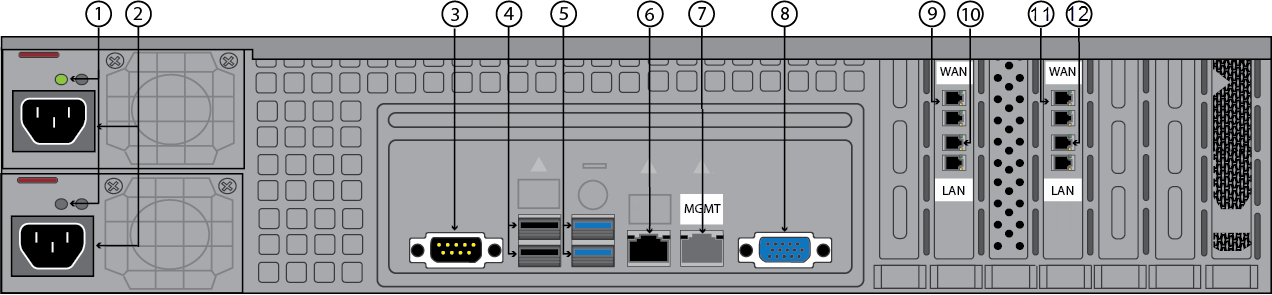
Barracuda Web Security Gateway 910 Rear Panel
The following image illustrates the Barracuda Web Security Gateway 910 rear panel ports and connectors.
The following table describes the Barracuda Web Security Gateway 910 rear panel ports and connectors. Note: Functionality of the WAN, LAN and AUX port lights vary by vendor and chip maker.
| Diagram Location | Component Name | Description |
|---|---|---|
| 1 | Power Lights | Displays:
|
| 2 | Hot Swappable Power Supplies (2) | Connection for the AC power cord, standard power supply |
| 3 | Serial Port | Connection for serial console cable |
| 4 | USB ports (2, 2.0) | Connection for USB 2.0 devices |
| 5 | USB ports (2, 3.0) | Connection for USB 3.0 devices |
| 6 | Auxiliary Port | Web interface management |
| 7 | Not used | Not used |
| 8 | Monitor Port | Connection for the monitor |
| 9 | WAN ports | 10G NIC is available with both copper and fiber (shown, for optional model 910B). |
| 10 | LAN ports | 10G NIC is available with both copper and fiber (shown, for optional model 910B). |
Barracuda Web Security Gateway 1010/1011
Barracuda Web Security Gateway 1010/1011 Front Panel
The following image illustrates the Barracuda Web Security Gateway 1010/1011 front panel and disk activity indicator lights.
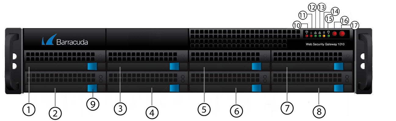
The following table describes the Barracuda Web Security Gateway 1010/1011 front panel power and disk activity indicator lights.
| Diagram Location | Component Name | Description |
|---|---|---|
| 1 | Hard Disk Drive | Location of disk drive |
| 2 | Hard Disk Drive | Location of disk drive |
| 3 | Hard Disk Drive | Location of disk drive |
| 4 | Hard Disk Drive | Location of disk drive |
| 5 | Hard Disk Drive | Location of disk drive |
| 6 | Hard Disk Drive | Location of disk drive |
| 7 | Hard Disk Drive | Location of disk drive |
| 8 | Hard Disk Drive | Location of disk drive |
| 9 | Hard Disk Drive Locks | Each drive has a lock/release button |
| 10 | Power failure | Indicates power supply failure |
11 | In older units: Temperature/fan failure | Indicates overheating / fan failure; most likelythe power supply fan. A loose connection could trigger the warning light. Try shutting down and reseating both power supply units. If that does not resolve the issue, request a new power supply. |
11 12 13 14 15 | In newer units: Information LED |
|
| 16 | Reset button | Resets the Barracuda Web Security Gateway |
| 17 | Power button | Powers the Barracuda Web Security Gateway on or off |
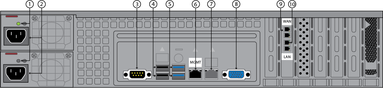
Barracuda Web Security Gateway 1010 Rear Panel
The following image illustrates the Barracuda Web Security Gateway 1010 rear panel ports and connectors.
Note : Newly manufactured 1010/1011 units have one pair of NIC ports (WAN and LAN) as shown below.
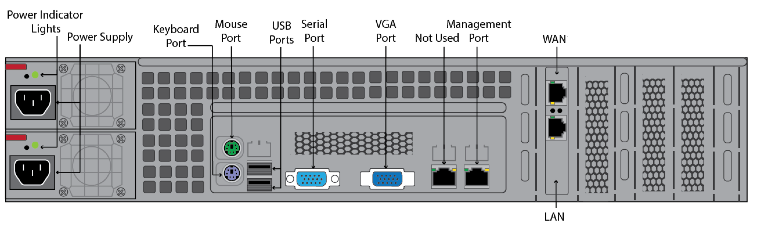
The following table describes the Barracuda Web Security Gateway 1010 rear panel ports and connectors. NOTE: Functionality of the WAN, LAN and AUX port lights vary by vendor.
| Component Name | Description |
|---|---|
| Hot Swappable Power Supplies (2) | Connection for the AC power cord, standard power supply |
| Power Lights | Displays:
|
| Mouse port | Connection for the mouse |
| Keyboard port | Connection for the keyboard |
| USB ports (2) | Connection for USB devices |
| Serial port | Connection for the serial console cable |
| VGA Port | Connection for the monitor |
| Management Port | Port for web interface management. |
WAN | WAN port connection: 10G NIC is available with both copper and fiber. |
| LAN | LAN port connection: 10G NIC is available with both copper and fiber. |
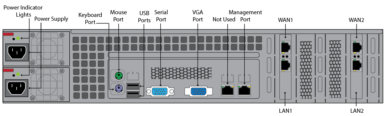
Barracuda Web Security Gateway 1011 Rear Panel
The following image illustrates the Barracuda Web Security Gateway 1011 rear panel ports and connectors. Note: Also note that newly manufactured 1011 units have only one pair of NIC ports (WAN and LAN).
The following table describes the Barracuda Web Security Gateway 1011 rear panel ports and connectors. NOTE: Functionality of the WAN, LAN and AUX port lights vary by vendor.
| Diagram Location | Component Name | Description |
|---|---|---|
| 1 | Power Lights | Displays:
|
| 2 | Hot Swappable Power Supplies (2) | Connection for the AC power cord, standard power supply |
| 3 | Serial Port | Connection for the serial console cable |
| 4 | USB ports (2) | Connection for USB devices |
| 5 | Not used | Not used |
| 6 | Not used | Not used |
| 7 | Auxiliary Port | Web interface management |
| 8 | Monitor Port | Connection for the monitor |
9 | WAN port | 10G NIC is available with both copper and fiber. |
| 10 | LAN port | 10G NIC is available with both copper and fiber. |
| 11 | WAN port | 10G NIC is available with both copper and fiber. |
| 12 | LAN port | 10G NIC is available with both copper and fiber. |
Note that newly manufactured 1011 units have only one pair of NIC ports (WAN and LAN) as shown below.