

Using the Linked Management feature you can cluster, or link two or more Barracuda Web Security Gateways together to provide synchronized configuration and policy settings across all systems. This article addresses the use case of choosing to designate one system in the cluster as the 'controller' if you only want to make configuration / policy changes to one system. These changes then automatically propagate to the others in the cluster. For basic linked management configuration of two Barracuda Web Security Gateways, click Help in the ADVANCED > Linked Management page of the web interface.
When to Not Use Linked Management
Some network environments may not be suitable to linking multiple Barracuda Web Security Gateway systems together. For example, if you have multiple network segments that each require different policies, it may be better to provide a dedicated, unlinked Barracuda Web Security Gateway for each segment. This way you can configure each Barracuda Web Security Gateway without the configuration settings propagating to the other systems. See How to Set Up Barracuda Cloud Control for information about managing multiple Barracuda Web Security Gateways (and/or other Barracuda Networks products) with unique configuration and policy settings on each system.
Example: Linking three systems
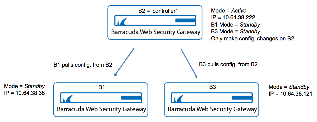
For example, you have three Barracuda Web Security Gateways and you want to synchronize configuration and policies across all three systems. In this example, system B2 is the ‘controller’ and systems B1 and B3 take their configuration and policies from B2. This configuration is illustrated in Figure 1. Steps to configure follow.
Figure 1. System B2 is the 'controller', and systems B1 and B3 pull their configuration from system B2
Step 1. Prepare each system for linking.
On each Barracuda Web Security Gateway, go to the ADVANCED > Linked Management page and create a Cluster Shared Secret. This is a password that is shared by all Barracuda Web Security Gateways in the cluster. Enter the same password on each system in the Cluster Shared Secret field in the Cluster Settings section of the page.
Step 2. Configure Centralized Management With Linked Systems
On system B2, go to the ADVANCED > Linked Management page. Set the MODE to Active.
On system B1, go to the ADVANCED > Linked Management page.
In the table, set mode for THIS machine, B1, to Standby.
In the Add System field, enter the IP address (or resolvable machine name) of B2.
Click Join Cluster. The configuration of system B2 will overwrite the configuration on this system (B1).
On system B3, go to the ADVANCED > Linked Management page.
In the table, set mode for THIS machine, B3, to Standby.
In the Add System field, enter the IP address (or resolvable machine name) of B2.
Click Join Cluster. The configuration on system B2 will overwrite the configuration on this system (B3).
On system B2, go to the ADVANCED > Linked Management page.
Make sure the MODE for B1 and B3 are both set to Standby. This tells system B2 that systems B1 and B3 will each pull their configuration from THIS system (B2).
On each of systems B1 and B3, go back to the ADVANCED > Linked Management page, and set the MODE for those systems to Standby.
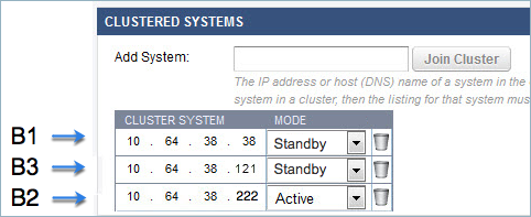
Figure 2. Clustered Systems table on ADVANCED > Linked Management page on system B2.
Note: In version 16.0 and higher, the Connection Status and Synchronization Latency columns are no longer included in the table.
Important Notes About Centralized Management
Any change you make on B2 will propagate to systems B1 and B3.
Any change you make on any other system in the cluster (B1 and B3) will be unique to that system and will NOT propagate to the other systems.
The Mode on each system does not matter to that system; it only matters to other systems in the cluster.
Systems on Standby PULL their configuration from units set to Active.
You can cluster mixed models, but keep in mind that some versions of lower models (410, for example) do not include the additional features available on higher models.
Data not propagated to each system in the cluster:
System IP Address/Netmask/Gateway
System DNS Servers
System Hostname
Cluster Hostname and settings
System Time Zone
System Password
Local Host Map
HTTP/HTTPS Port (must be the same value on all machines)
HTTPS Certificate/Settings (includes WSA certificates used for secure logins and HTTPS decryption and root certificates for LDAPS.)
WSA Hostname
Ethernet Port Speeds/Duplex/MTU
System Alert Email Address
Static Routes
Local Redirect IP (Block Page IP. Located under Block/Accept > Configuration)
Appearance Logo
Appearance URL
Syslog Servers
VLAN Name
VLAN Interface
Virtual Interface
IP Route Configuration
Cluster Shared Secret
Cluster Systems
HTTPS UI port
Use HTTPS UI only
Secure Administration Certificate Config (includes uses of HTTPS blockpage and Chromebook security extensions)
Operating Mode
Peer Proxy Enable/IP/Port
Connect to Cloud Control
Proxy Auth Helper Threads/Custom
WCCP Configuration settings
Schedule Report
Delegated Admin Users
Auxiliary Port Enable/IP/Netmask/Gateway
Offline Update
Backup options/settings
Audit log entries of primary device
WPAD or PAC files used on WSG device