

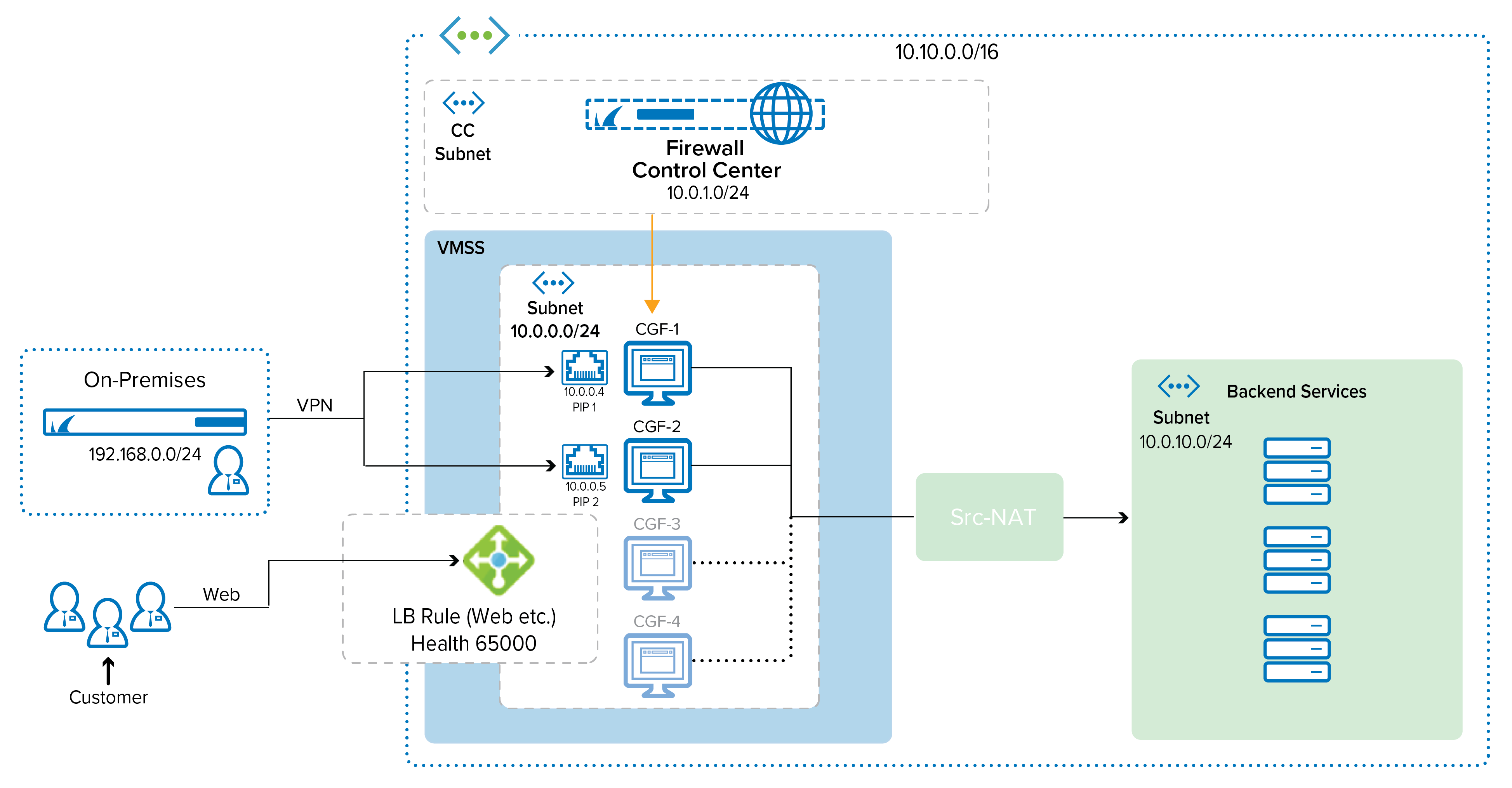
The following example explains Azure active-active deployment with load balancing and and VPN termination. The CloudGen Firewall configuration in Microsoft Azure supports repositories, conf templates, and the distributed firewall. For more information, see Repositories, Distributed Firewall, and How to Work with Configuration Templates on Different Levels in the Configuration Tree.
Before You Begin
Before proceeding with deploying the Barracuda CloudGen Firewall HA template, make sure that your network infrastructure meets the service requirements listed in CloudGen Firewall Active-Active Performance in Microsoft Azure.
Otherwise, do the following:
- Create a resource group
- Create a storage account
- Create VNET and subnet
- Get a CGF image
For more information, see How to Create a Resource Network in Azure.
Step 1. Deploy a Barracuda Virtual Machine Scale Set
- Log into your Azure Portal.
- Go to the resource group created in the prerequisites. (See the Before You Begin section for more information.)
- Click + to create a new resource.
- Search for
VMSSin the Marketplace. - Choose Virtual machine scale set.
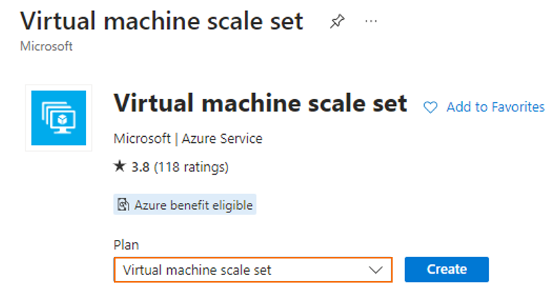
- Click Create.
- On the next page, configure the following settings:
- Virtual machine scale set name – Enter a name.
- Region – Select your region.
- Availability zone – Select your preferred availability zone.
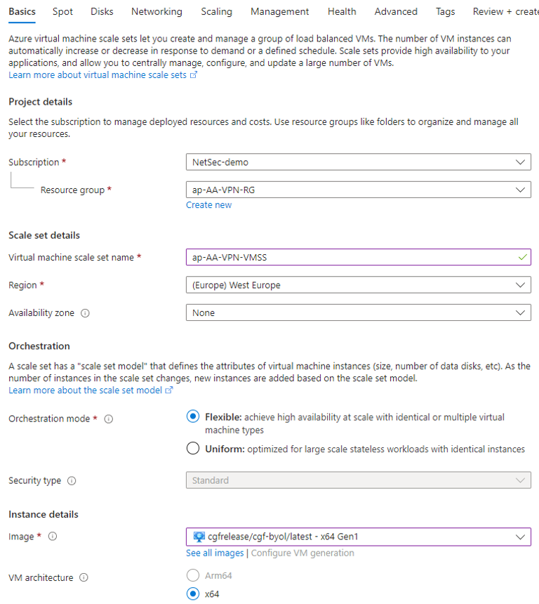
- Image – Select image cgf/cgf-byol/latest.
- VM Architecture – Select x64.
- Size – Select the VM size.
- Username – Enter a username.
- Password – Enter a password.
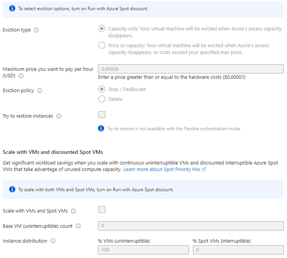
- On the next page, configure Spot settings according to your requirements.
- On the next page, set up Disks according to your requirements.
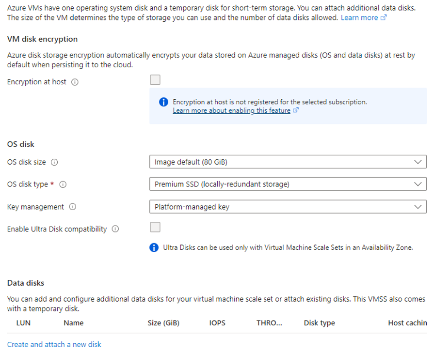
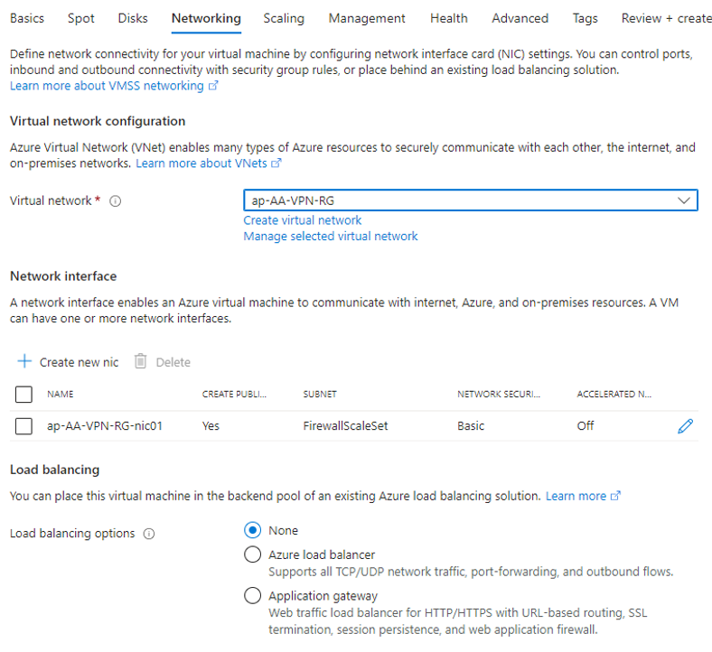
- On the next page, configure following settings:
- Virtual network – Select the virtual network created in the "Before You Begin" section.
- Edit NIC – Select the subnet you want to deploy the scale set to.
- Load balancing options – Select None. The load balancer will be added later.
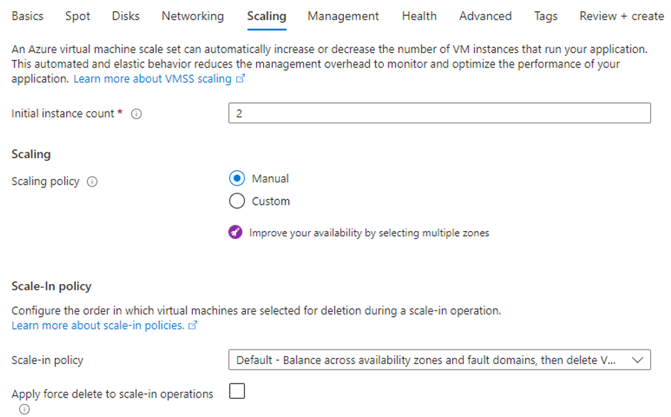
- On the next page, choose your scaling settings:
- Initial Instance count – Enter
2 - Scaling Policy – Select Manual.
- Initial Instance count – Enter
- On the next page, choose the storage account or create a new one.
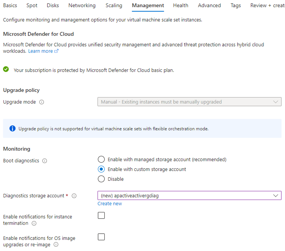
- Click Next to continue on the Health page.
- Click Next to continue on the Advanced page.
- Optional: Add a user data script to get retrieve par file configuration in case the instance is relaunched.
- Click Next to continue on the Tags page.
- Verify the settings on the Review and Create page.
- Click Create to create the scale set.
Step 2. Virtual Machine Scale Set – Post-Deployment Steps
Go to the resource group the scale set has been deployed to.
- Select the Network Security Group created along with VMSS.
- Configure inbound security rules – Allow port 443, 807, 801, 22, 691
- Configure outbound security rules according to your specification.
- Go back to the resource group.
- For each VMSS instance, select the corresponding network interface.
- In IP configuration, make sure that Enable IP forwarding is selected.
Step 3. Create a Load Balancer
- From the resource group, click + to create a new resource.
- Type in
Load Balancerand select the resource from the list. The Load Balancer page opens.
- Click Create to create a new load balancer.
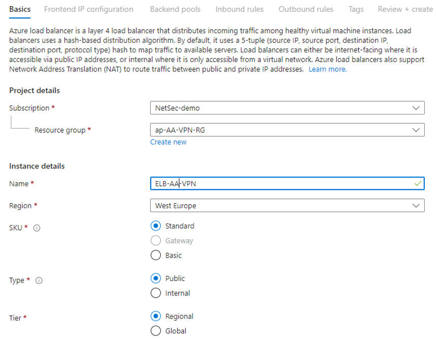
- On the next page, choose your settings:
- SKU – Select the desired SKU (default: Standard).
- Type – Select Public.
- Tier – Select Regional.
- On the next page, configure your frontend IP settings:
- Click Add a frontend IP.
- The Add Frontend IP window opens. Configure the following settings:
- Name – Enter a descriptive name.
- Virtual Network – Select the virtual network where the VMSS resides.
- Subnet – Select the subnet where the VMSS resides.
- Assignment – Select Static.
- IP Address – Select Public IP.
- Availibility Zone – Select Zone-redundant.
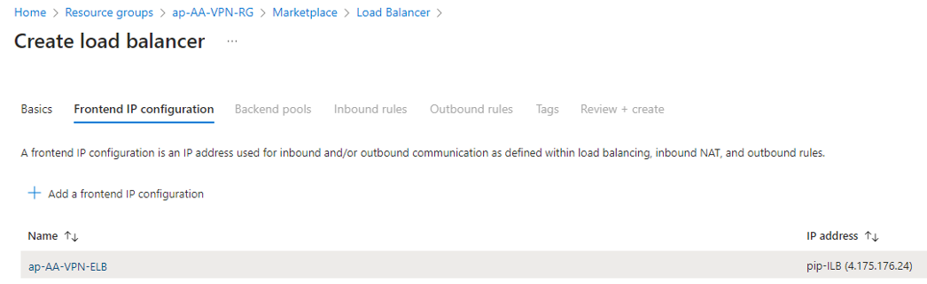
- Click Save.
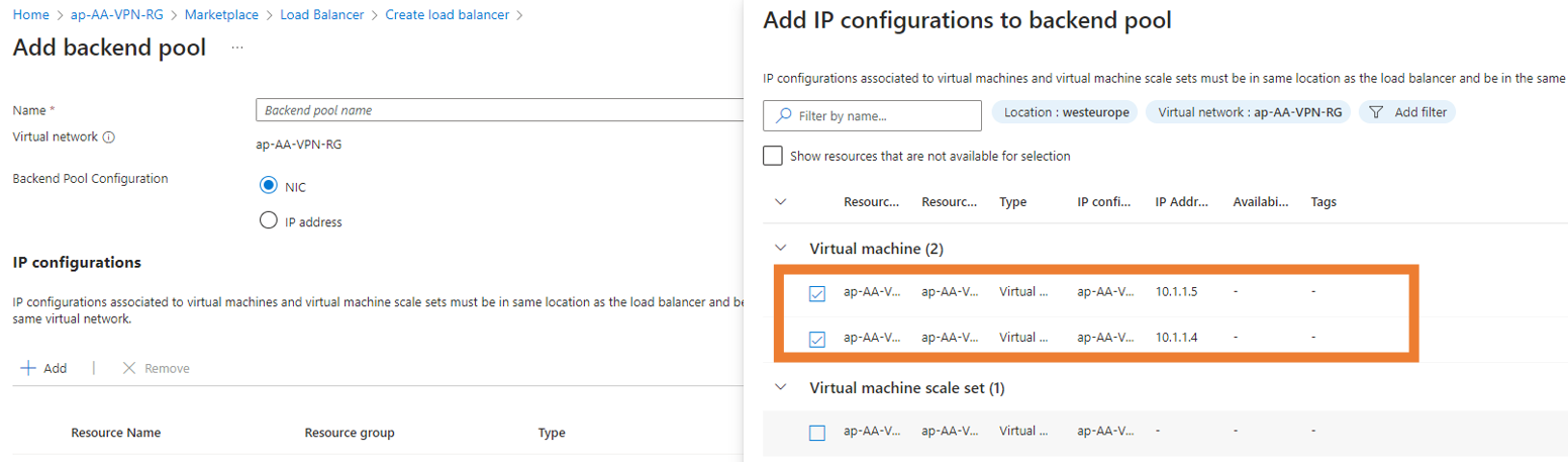
- Proceed with the Backend pool:
- Provide a Name.
- Click + to add a backend pool.
- Select the related NICs from VM scale set.
- Click Add and Save.
- Click Next to continue with Inbound rules:
- Click + Add a load balancing rule, and specify the following settings:
- Name – Enter a name.
- IP Version – Select IPv4.
- Frontend IP address – Select the IP address.
- Backend Pool – Select the backend pool.
- Protocol – Select TCP.
- Backend Port – Enter
80 - Port – Enter
80 - Health Probe – Create a new entry.
- Name – Enter a name.
- Protocol – TCP
- Port – Enter
65000 - Interval seconds – Enter
5
- Idle timeout – Select 4 (default)
- Enable TCP Reset – Leave unchecked.
- Floating IP – Leave unchecked.
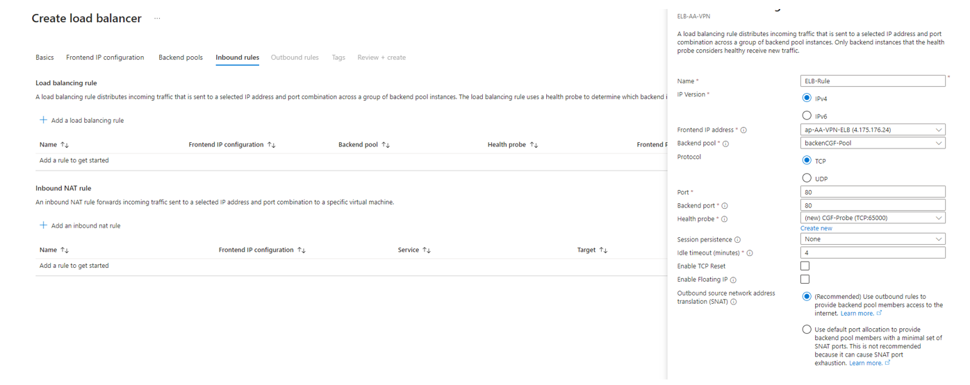
- Click Save.
- Click Next to proceed to Outbound rules.
- Click Next to proceed to Tags.
- On the Review and create page, verify your settings.
- Click Create.
Step 4. Add the Firewall Instances to the Control Center
Add the CloudGen Firewall instances created with the Firewall VM scale set to the Control Center. For more information on managed firewalls, please refer to How to Import an Existing CloudGen Firewall into a Control Center.
Create a cluster- / range-level repository for the linked configuration management. For more information, see Repositories.
Step 5. Set Up Rules and Repositories, and Link Them to Your Firewall Scale Set
- On the Control Center, go to Configuration Tree > your Range > your Cluster > your Box > Assigned Services > Firewall.
- Right-click Forwarding Rules and select Copy to Cluster repository.
- Provide a Name and copy the node.
- Open the created repository.
- Click Lock.
- Add an App Redirect Rule rule for load balancing heath check.
- Source – Select Any.
- Services – Add
65000 TCP - Destination – Select DHCP1 Local IP.
- Redirection – Enter
127.0.0.1:450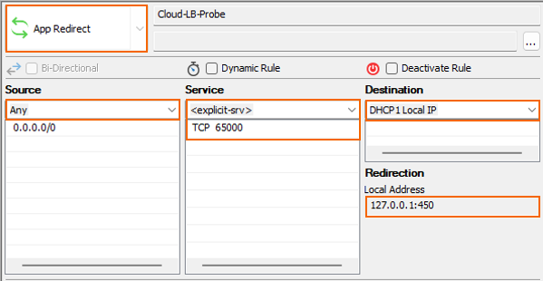
- Add a Dst NAT rule to access the back-end server:
- Source – Select Any.
- Services – Add the ports for required services.
- Destination – Select DHCP1 Local IP.
- Redirection – Enter the IP address of your back-end server.
- Connection Method – Select Dynamic NAT.
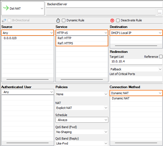
- Click OK.
- Click Send Changes.
- Close the repository window.
- Right-click on the firewall repository and select Multiple Object Action.
- Select all firewall instances for the corresponding scale set.
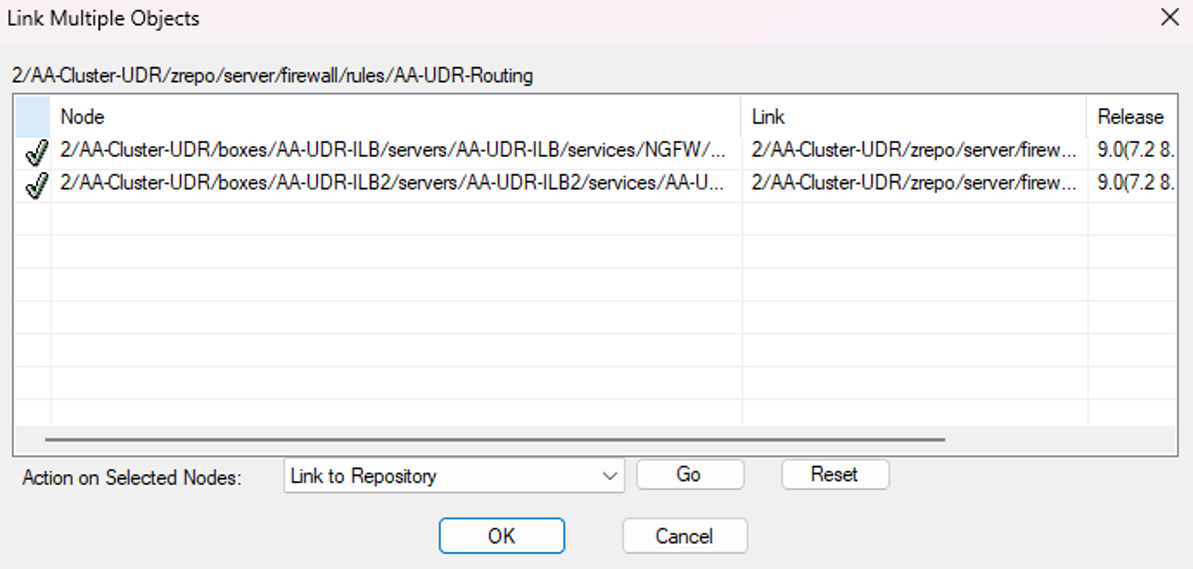
- Select Link To repository > Go.
- Click OK.
- Click Activate.
Step 6. Set Up a VPN Key for the Active-Active Site-to-Site Tunnel
For reference and more detailed information, please refer to the Site 2 Site VPN documentation.
For each box in the active-active setup, perform the following steps:
On the Control Center:
- Go to Configuration > Configuration Tree > your Range > your Cluster > your Box > Assigned Services > VPN Service > VPN Settings.
- In the left menu, select Service Keys.
- On the first instance, create a new service key and copy the private key to clipboard.
- On following instances, paste the private key copied in the previous step.
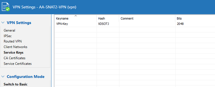
- On the last instance, copy the public key to clipboard.
Repeat the steps above to create a new dedicated key for the on-premises instance.
Step 7. Create a Site-to-Site VPN Tunnel
For the on-premises instance, perform the following steps:
On the Control Center:
- Go to Configuration > Configuration Tree > your Range > your Cluster > your Box > Assigned Services > VPN Service > Site to Site.
- Create a new TINA Tunnel:
- Configure Local Networks.
- Configure Remote Networks.
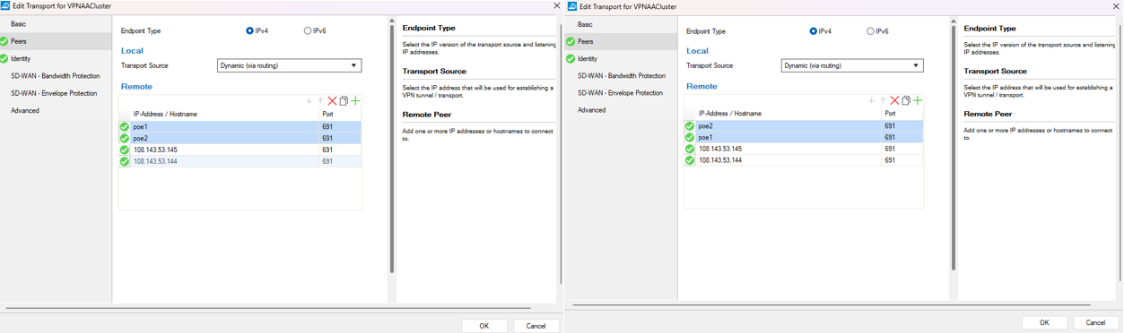
- Configure Transport settings:
- Basic – Set to Active.
- Peers – Add remote public IP addresses for each instance in the active-active setup.
- Identity – Paste the remote pubic key from Step 6.
Set the remaining parameters according to your requirements.
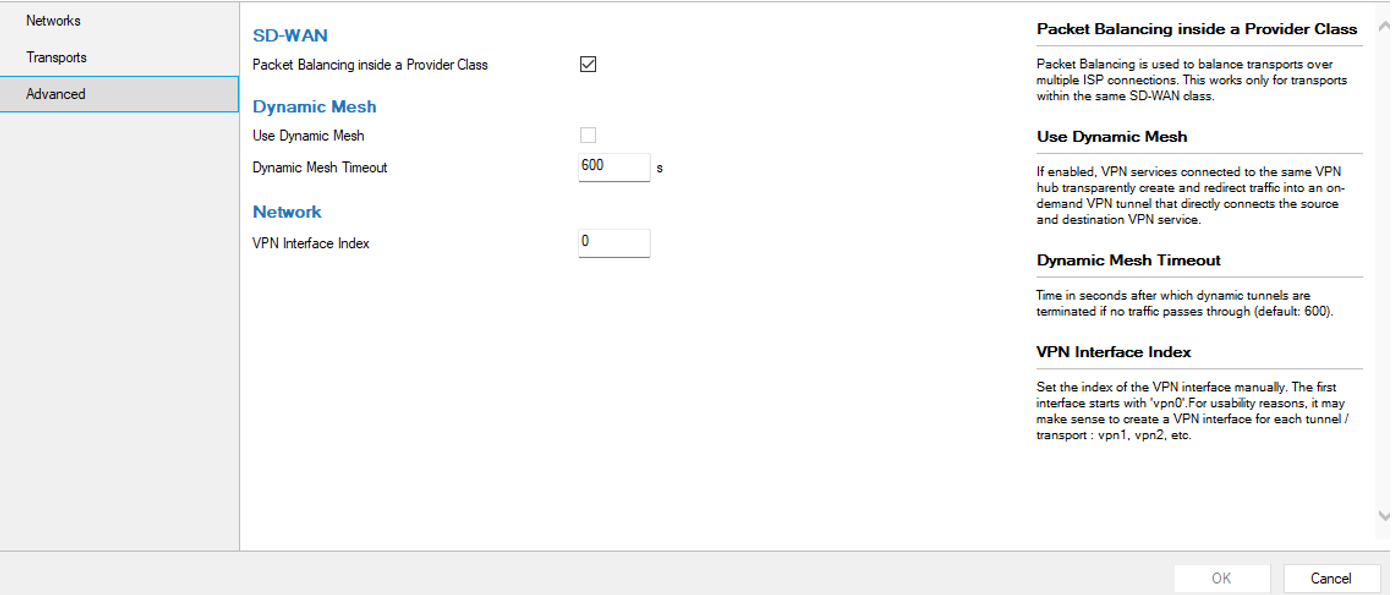
- Select the box Packet balancing inside provider class to distribute the session.
- On the Center, go to Configuration > Configuration Tree > your Range > your Cluster > your Box > Assigned Services > VPN Service > VPN Settings.
- In the left menu, select Service Keys.
- Copy the Public Key from the Service Key section to clipboard.
For each firewall in the scale set, perform the following steps:
On the Control Center:
- Go to Configuration > Configuration Tree > your Range > your Cluster > your Box > Assigned Services > VPN Service > Site to Site.
- Create a new TINA Tunnel:
- Configure Local Networks.
- Configure Remote Networks.
- Configure Transport settings:
- Basic – Set to Passive.
- Peers – Add remote network
0.0.0.0/0 - Identity – Paste the remote pubic key from Step 6.
Set the remaining parameters according to your requirements.
- Select the box Packet balancing inside provider class to distribute the session.
Step 7. Verify the Setup
Your Barracuda CloudGen Firewall instances should have at least one transport connected to one instance. Some transports might appear offline since the secondary instance serves as fallback. We recommend that you test the fallback behavior.
Next Steps
You can now configure your routing rules on the CloudGen Firewalls according to your individual requirements.