Protecting highly dynamic AWS resources with a static firewall setup is neither efficient nor economical. A CloudGen Firewall Auto Scaling Cluster scales with demand, thereby creating a cost-effective, robust solution for securing and connecting to your cloud resources. The firewall cluster can be deployed either to integrate with existing resources in an AWS region, or as part of an auto scaling application. Both options offer an integrated Barracuda Web Application Firewall (WAF) as a second security tier. The firewall cluster integrates tightly with AWS services and APIs. Configuration changes are synchronized securely over the AWS backend, with all instances sharing the same configuration. The admin can configure the changes like a single firewall instance. The firewall cluster is highly available and scalable over multiple AWS Availability Zones, without any single point of failure such as additional management or worker node instances. The firewall cluster uses the PAYG image of the Barracuda CloudGen Firewall in the AWS Marketplace. This allows you to quickly deploy without the need for long-term licensing commitments. CloudGen Firewall clusters cannot be managed by a Firewall Control Center.
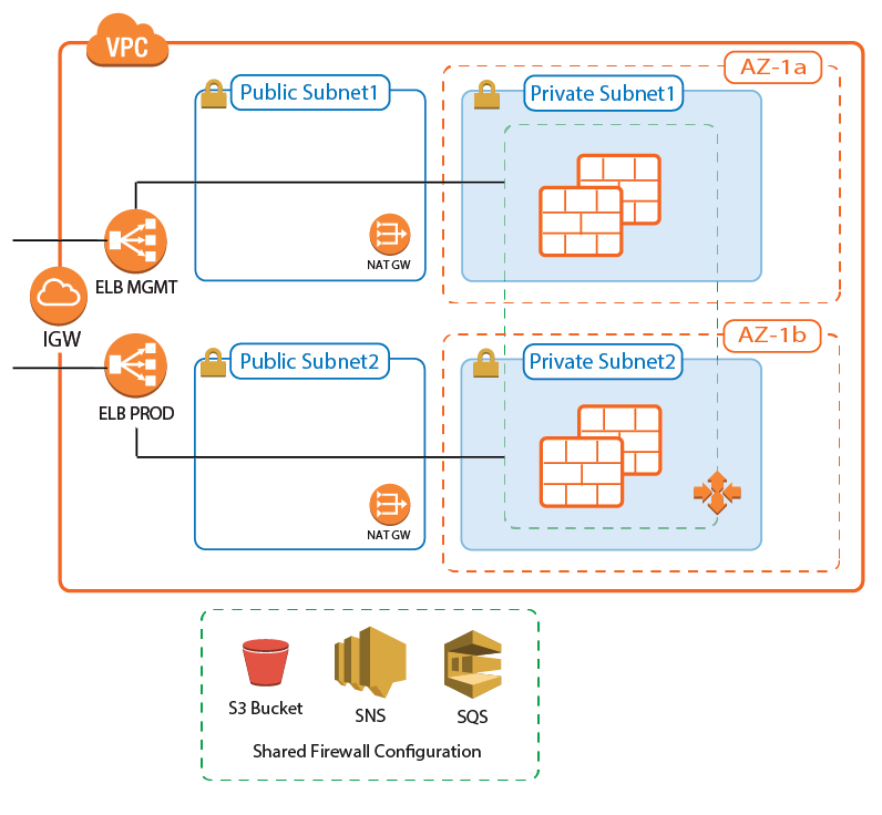
Use Cases for a CloudGen Firewall Auto Scaling Cluster
- Secure Remote Access – Client-to-site VPN, CudaLaunch, and SSL VPN using the TINA VPN protocol.
- Edge Firewall – Scan for malicious traffic using the built-in IPS and handle access to resources via access rules.
AWS Architectures for CloudGen Firewall Auto Scaling Clusters
Since there are no external dependencies, the CloudGen Firewall cluster can either be used as a drop-in solution to protect your existing applications in the same AWS region, or it can be included as part of the architecture of your application.
Transit VPC with VPC Peering
The firewall cluster is used in a Transit VPC configuration. The firewall VPC acts as a hub securing all traffic in and out of the peered VPCs. Two peered VPCs must be in the same AWS region, but can be in different AWS accounts. Transitive peering is not possible; therefore, resources in two VPCs both peered with the Transit VPC cannot communicate with each other. Incoming traffic is handled via access rules allowing access to the backend resources based on the access rule matching criteria, such as source, user, or time. Since the VPC for the firewall cluster is separated from the VPCs containing the applications, rapid iteration of the applications is possible without requiring changes to the firewall cluster. For example, in a typical scenario with production, engineering, and development VPCs, granular access rules allow the firewall admin to separate users based on their role:
- Traffic to production VPCs is secured by IPS and, optionally, forwarded to a Web Application Firewall cluster.
- QA and developers log in via client-to-site VPN. The firewall uses the user information to allow access only to their respective VPCs.
- Admins are in a special group, allowing them backend access to production and QA VPCs.
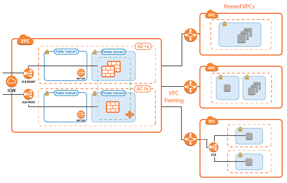
Transit VPC with VPC Peering and Barracuda Web Application Firewall Auto Scaling Cluster
A variation of the transit VPC includes an additional Web Application Firewall cluster behind the CloudGen Firewall cluster. The Barracuda Web Application Firewall and CloudGen Firewall F can work in tandem to block IP addresses from which malicious activity was detected. Whereas the WAF is very good at detecting application layer attacks, the CloudGen Firewall is more efficient on the network layer. Connections blocked by the firewall IPS are never forwarded to the WAF, thereby freeing resources that would otherwise have to be used to block known-bad connections.
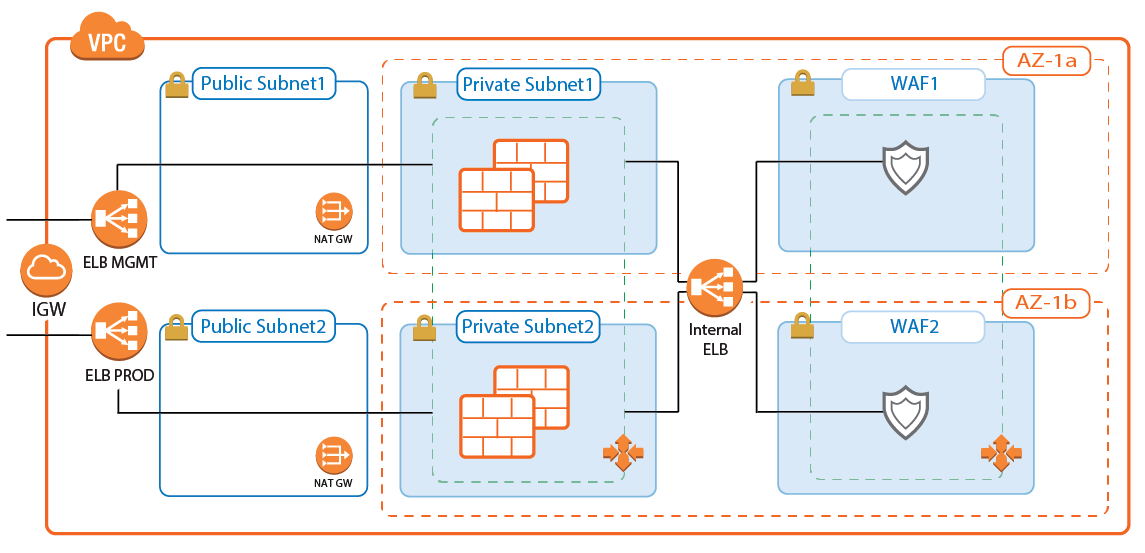
Integration into AWS Architecture
You can integrate the firewall cluster into your existing architecture. Use the default CloudFormation template as reference. To be able to reuse the configuration, configure the CloudGen Firewall cluster one time via Barracuda Firewall Admin, and then replicate the S3 bucket to reuse the configuration.
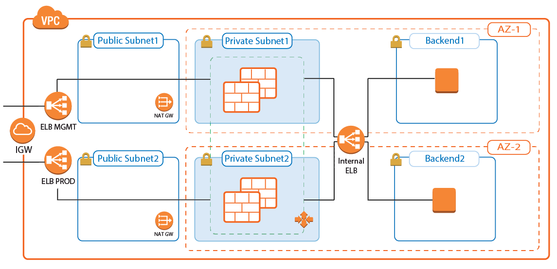
Deploying a CloudGen Firewall Auto Scaling Cluster
The firewall cluster must be deployed via CloudFormation template. The template deploys a VPC with public and private subnets in two Availability Zones. In the private subnets, the firewall cluster is deployed. In the public subnets, the Elastic Load Balancer (ELB) and two NAT gateways are deployed (one for each Availability Zone). The NAT gateways are required for the firewalls to be able to access the AWS backend. APIs are required to enable the secure configuration sync over the AWS backend.
- Create an IAM role for the firewall cluster. For step-by-step instructions, see How to Create an IAM Role for a CloudGen Firewall in AWS.
- Download the NGF_Autoscaling.json template and parameter file from the Barracuda Network GitHub account: https://github.com/barracudanetworks/ngf-aws-templates/tree/master/ASG.
- Accept the Software Terms for the Barracuda CloudGen Firewall PAYG image in the AWS Marketplace.
- Create a parameter template file containing your parameters values.
Deploy the autoscale.json CloudFormation template via AWS CLI or AWS console.
aws cloudformation create-stack --stack-name "YOUR_STACK_NAME" --template-body YOUR_S3_BUCKET/NGF_Autoscaling.json --parameter YOUR_S3_BUCKET/NGF_Autoscaling_parameters.json
During deployment, the following resources are created by the template:
- VPC with private and public subnets in two Availability Zones.
- Two ELBs: one for management connections, the other for VPN and SSL VPN services.
- One S3 bucket.
- Automatically created SNS and SQS queues.
- Two NAT gateways.
- A Launch Configuration and Auto Scaling group for the firewall. The Barracuda CloudGen Firewall PAYG image must be used.
- Scaling policies using the number of client-to-site VPN tunnels.
After stack creation is complete, the FQDN of the ELB are listed in the Output tab.
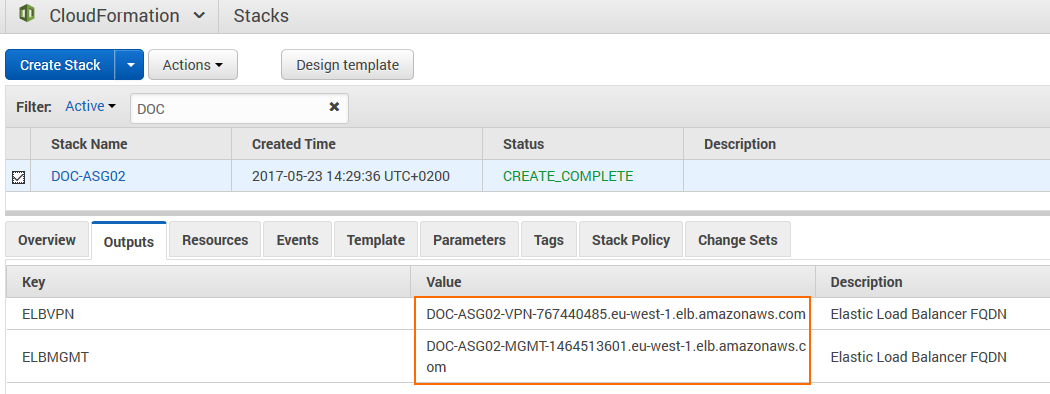
For step-by-steps instructions, see How to Deploy a CloudGen Firewall Auto Scaling Cluster in AWS.
Remote Access
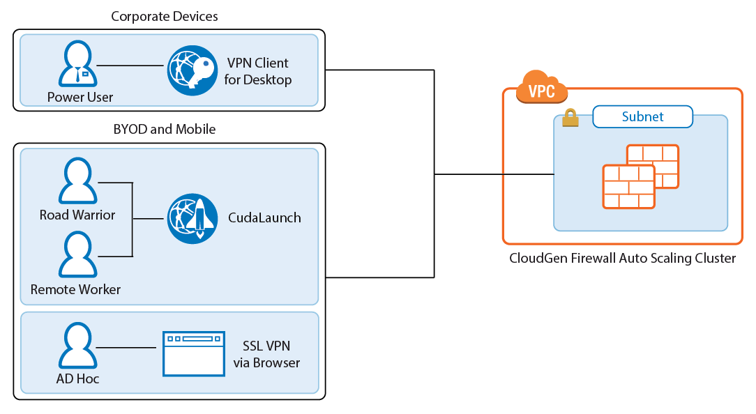
Remote Access features offer remote users secure access to their organization's cloud applications and resources from virtually any device. Depending on the type of access users require, they can choose between the full client-to-site VPN or the SSL VPN web portal.
Client-to-Site VPN
The client-to-site VPN uses the TINA VPN protocol on TCP port 691 to connect to the firewall cluster. TINA is designed to overcome limitations imposed by the IPsec protocol and offers immunity to NAT devices or proxies, heartbeat monitoring, and fast failover support. VPN clients can be authenticated through client certificates, external and internal authentication schemes, or a combination thereof. Supported VPN clients are:
- Barracuda VPN / NAC Client for Windows, macOS, Linux, and OpenBSD.
- CudaLaunch for Windows, macOS, iOS, and Android version 2.3.0 or higher.
On the CloudGen Firewall Auto Scaling Cluster, configure the VPN service for client-to-site connections by adding one or more VPN group policies. Incoming client-to-site connections are matched to a VPN group policy based on the group policy condition. The first matching VPN group policy is chosen. VPN group policy conditions allow you to define the following criteria:
- Group patterns from external authentication schemes
- X.509 certificate conditions
- VPN clients
- Source IP address or network for the VPN clients
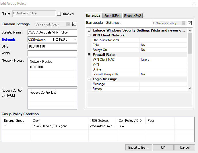
For step-by-step instructions, see How to Configure a Client-to-Site VPN Group Policy for an CloudGen Firewall Auto Scaling Cluster in AWS.
SSL VPN and CudaLaunch
The SSL VPN service provides seamless integration without having to install a client app. For a richer level of remote access, CudaLaunch works with the SSL VPN service to provide more advanced SSL VPN features such as SSL tunneling or native app support. The number of simultaneous users using the SSL VPN is limited only by the performance and number of firewall instances in the Auto Scaling group. Since the SSL VPN service is not designed to share session information between the members of the Auto Scaling group, the ELB must be configured to use sticky sessions and SSL offloading to ensure that the individual client will always be redirected to the same firewall instance. SSL VPN resources can be accessed by the following clients:
- CudaLaunch
- SSL VPN web interface – All modern browsers.
For step-by-step instruction, see How to Configure the SSL VPN Services for AWS Auto Scaling Clusters.
Firewall and IPS
The firewall cluster secures incoming and outgoing traffic from your AWS resources. This can be traffic from AWS instances in peered VPCs or instances in the private networks of the VPC. If enabled on the access rule matching the traffic, the IPS engine on the firewall continuously compares the packet stream with the internal signatures database for malicious code patterns. If malicious packets are identified, traffic is either reported or dropped, depending on the configuration of the IPS. To ensure that the latest patterns are used, the IPS patterns are updated automatically from the Barracuda Networks download servers.
When used in combination with a Barracuda Web Application Firewall cluster, the IPS and access rules block network layer attacks, saving processing power on the WAF for layer 7 attacks. For traffic to be able to flow through the firewall cluster and back, all access rules must use both source and destination IP address translation (NAT). This ensures that traffic will go back over the same firewall. The CloudGen Firewall Auto Scaling Cluster cannot be used as the default gateways for your AWS resources.
Configuration and Monitoring
Barracuda Firewall Admin is a stand-alone, multi-administrator Microsoft Windows application used to administer CloudGen Firewalls. Managing the configuration of the firewall cluster is very similar to managing a single firewall. Connect to the cluster through the ELB with a listener on TCP 807. This instance now transparently redirects the connections to other instances in the cluster as needed. Information on some tabs, such as the CONFIGURATION and VPN tabs, are aggregated by combining the data from all firewalls in the cluster. The FIREWALL > History page also displays connection data from all firewalls in the cluster. All other tabs and configuration elements display only the information of the firewall instance Firewall Admin is currently connected to.
- Aggregated tabs – All pages in the CONFIGURATION tab.
- Aggregated pages – VPN > Client-to-Site , VPN > Site-to-Site and FIREWALL > History.
- Aggregated dashboard elements – Updates element on the General dashboard.
On pages that display aggregated data from all firewall instances in the cluster, use the Instance ID column to filter or group the information by instance.
Login and Default Password
Connect to the firewall cluster via Firewall Admin using the FQDN of the ELB with a listener on TCP 807. The default password is the instance ID of the first instance in the Auto Scaling group. Go to the Instance tab of the Auto Scaling group and locate the instance that is protected from scale in to identify the first instance.

- IP Address /Name – Enter the DNS name of the management ELB in front of the firewall cluster.
- User – Enter
root. - Password – The default password is the instance ID of the first instance.
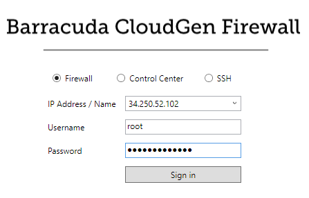
After logging in the first time, you are prompted to change your password.
Log Streaming to AWS CloudWatch
Log files stored on the firewall instances themselves are ephemeral. As soon as an instance is terminated, the log files are deleted with it. To keep the log files for later analysis, troubleshooting, or regulatory reasons, use syslog streaming on the firewalls to send them to AWS CloudWatch. There, the logs can be placed in groups, filtered, or processed further.

For step-by-step instructions, see How to Configure Log Streaming to AWS CloudWatch.
Monitoring and Statistics through AWS CloudWatch
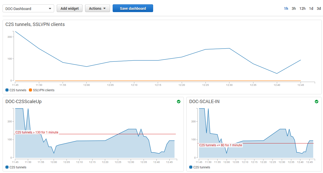
Each firewall in the cluster sends both basic and custom firewall metrics to AWS CloudWatch. Using AWS CloudWatch, you can monitor and visualize these metrics through CloudWatch alarms and dashboard widgets. Monitoring alarms through the dashboard widgets allows the admin to see why auto scaling policies were applied and offers the data necessary to make improvements. The granularity at which the metrics are published can be changed. By default, metrics are published every 5 minutes. Enable detailed monitoring to lower the granularity to 1 minute. This can be configured in the template by adding this parameter to the AutoScalingGroup (ASG) resource in the template.
    "ASG": {
            "Type": "AWS::AutoScaling::AutoScalingGroup",
            "Properties": {
            [....]
                "MetricsCollection": [{
					"Granularity" : "1Minute"
				}],
            [....]
Monitoring via Firewall Admin
For remote access and firewalling workloads, the firewall cluster Firewall Admin provides more detailed, up-to-date information than is accessible through CloudWatch.
When logged in via Firewall Admin, client-to-site and SSL VPN tunnels are listed on the VPN > Client-to-Site and VPN > Status pages. The data in the VPN tab is aggregated from all firewall instances in the ASG. The pages list all available client-to-site and SSL VPN tunnels. On the VPN > Status page, the status is indicated by a colored icon In the Tunnel column:
- Blue – The client is currently connected.
- Green – The VPN tunnel is available, but currently not in use.
- Grey – The VPN tunnel is currently disabled. To enable the tunnel, right-click it and select Enable Tunnel.
To troubleshoot individual connections, click the client-to-site tunnel in the list and then see the error messages in the inf columns of the Drop Cache and Access Cache tabs.

For more information about the VPN > Client-to-Site page, see VPN Tab.
For more information about the FIREWALL > History page, see History Page.
Scaling Policies - Scheduled Actions
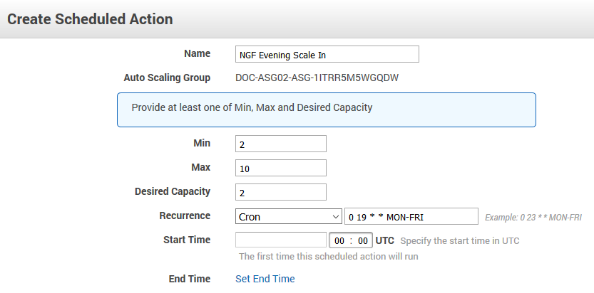
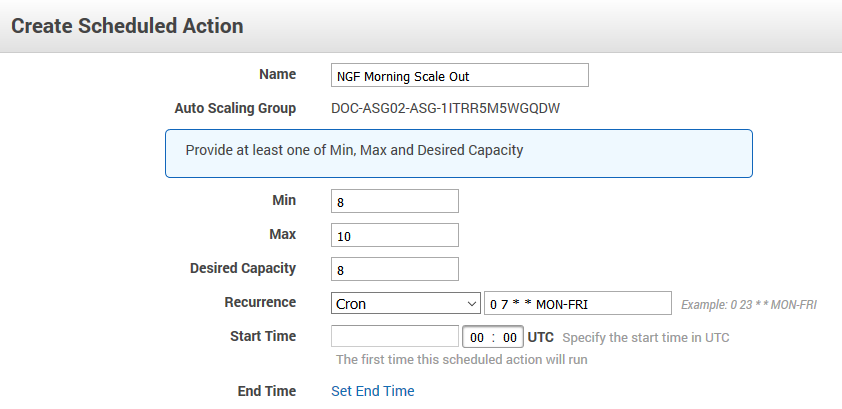
The cluster scales to a predefined number of instances according to the time of day or date. Unhealthy or terminated instances are automatically replaced. Use scheduled scaling for predictable workloads, or to reduce the number of instances overnight when the load is low. Since one instance in the cluster is always protected from scale-in, it is not possible to completely shut down the firewall cluster. To retain high availability, at least two instances are needed. Scheduled actions are configurable in the Scheduled Actions tab of the Auto Scaling group settings.
Example scheduled action that scales up the cluster during the day Monday through Friday and scales back during the night and on weekends:
Scaling Policies - Dynamic Scaling
To optimize the firewall cluster to your workload, you need to select the metrics, and know how to interpret the values and the resulting action. Scaling metrics should be selected based on the use case. For example, a firewall cluster with a lot of client-to-site VPN connections should scale on the C2S Tunnels metric. If firewalling is the biggest part of the workload, it can also scale on the throughput or number of sessions, or number of dropped sessions. To achieve high availability, the firewall cluster must always use a minimum of two instances in two different Availability Zones.
Select the Relevant Metrics
To scale your firewall cluster dynamically, you must first select the metrics upon which you are going to the scale. The individual data points of the metrics can be averaged (relative performance metrics) or summed up (absolute performance metric) over a time period when creating the CloudWatch alarms. If you are adding up the data points (SUM), make sure to set the time period to match the metric collection granularity: One minute for detailed monitoring, five minutes for normal monitoring. For each metric, define upper and lower limits at which the cluster is scaled out and in. Make sure to leave enough room between the scale-out and scale-in thresholds to avoid the cluster from scaling in and out too frequently, resulting in additional cost and lower performance of the cluster. To avoid additional scaling actions before the previous action has taken effect, configure the ASG to use a cool-down period of at least 10 minutes (600 seconds). Use the CloudWatch widgets to visualize your alarms. This helps you to adjust the values to fit your workload.

It may also help to think about how the data points collected from the firewall cluster are used in the CloudWatch alarm:
- Averaged metrics (default) – Use average values over a time period that uses multiple metrics. Use longer time periods for the threshold to be more inert; shorten the time period to be more responsive. Setting the time period to a value that is too short causes the cluster to scale out and in too often, causing unnecessary cost. If in doubt use relative metrics.
- Absolute metrics – Set the CloudWatch alarm to add the metrics collected from the firewall cluster in the same time period that the metrics are published in. For detailed monitoring, select 1 minute, for standard monitoring 5 minutes. Using absolute values are a good choice if you want to define exact correlations between the value of a metric and the number of instances. For example: 500 client-to-site tunnels always equals 2 firewall instances; 1000 client-to-site tunnels always equals 5 instances, and so on. Absolute metrics are a good choice when the number of instances needed is non-linear.
Simple or Step Scaling
The next thing to define is if the scaling policy should always scale the same amount every time the alarm is triggered, or if there are different steps depending on by how much the value differs from the threshold value set in the alarm. Using a simple one-step scaling policy does not cope well with quickly increasing demand. By the time the scaling action has finished, the demand may have outpaced the number of available instances, forcing to scale multiple times to achieve the desired performance. This effect can be mitigated by scaling up multiple instances each time the alarm is triggered, potentially overshooting the required number of instances and incurring costs for the extra instance until the scale-in policy removes it.
For a more efficient scaling policy that covers both the slowly rising demand and quick changes, create a policy containing multiple steps. This allows you to immediately scale to the correct number of instances, thereby improving the efficiency of the cluster. Depending on the size of the step, increase the cool-down period after scaling to avoid scale-in policies from removing instances too quickly before the increased number of instances take effect.
Add Instances or Go to Exact Capacity when Scaling
The last decision before you can put your scaling policy into action is whether to simply add capacity when the alarm is triggered, or to use exact capacity numbers to match. For alarms using averaged metrics, add capacity; for absolute (SUM) metrics, set the exact capacity. Exact capacity is mainly used for non-linear workloads, whereas adding capacity is more flexible and requires less testing because the scaling threshold values are the same no matter how many instances there are in the cluster.
For step-by-step instructions, see How to Configure Scaling Policies for a CloudGen Firewall Auto Scaling Cluster.
Force Reconnect on Scaling Action for Client to Site VPN
A custom parameter in the firewall can force a redistribution of all client-to-site connections on each scaling event of the cluster. All clients automatically reconnect, thereby evening out the load. Depending on the type of traffic going through the client-to-Site VPN, this action may not be transparent to the remote users because active sessions may time out and, therefore, require the user to reconnect to the backend service.
For step-by-step instructions, see How to Configure a Client-to-Site VPN Group Policy for a CloudGen Firewall Auto Scaling Cluster in AWS.
Installing Hotfixes
Hotfixes are published by Barracuda Networks when an issue requires immediate attention, such as newly discovered security vulnerabilities or critical bugs in the firmware. Hotfixes are installed through the Firewall dashboard in Firewall Admin. New instances in the cluster automatically install the same hotfixes when the cluster scales. Most hotfixes reboot the firewall. Consider this when setting the cool-down value for scaling actions because it will take longer for an instance to be ready when multiple hotfixes need to be installed.
For step-by-step instructions, see How to Install Updates via Barracuda Firewall Admin.
Firmware Update via CloudFormation Stack Update
Although possible, it is not recommended to install firmware updates like hotfixes through the Update element on the Firewall Admin dashboard. Instead, replace the AMI in the parameter file of your template and update the CloudFormation stack. The AMI for the new firmware version is listed in the Manual Launch tab of the listing for the Barracuda CloudGen Firewall PAYG image in the AWS Marketplace.
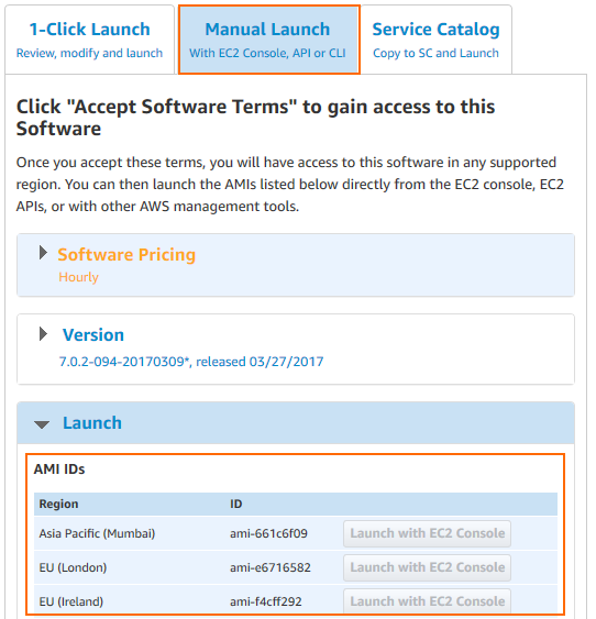
If your templates are stored in an S3 bucket, enter this AWS CLI command to update CloudFormation stack:
aws cloudformation update-stack --stack-name "YOUR_STACK_NAME" --template-body YOUR_S3_BUCKET/autoscale.json --parameter YOUR_S3_BUCKET/autoscale_parameters.json
After updating the stack, scale down to one instance and manually terminate the instance protected from scale-in through the AWS CLI or EC2 web portal. All new instances that are launched now use the new AMI in the updated launch configuration. If the instance that is protected from scale-in is not terminated manually, the firewall cluster will be in an inconsistent state.
Backup / Restore
Creating a backup and restoring the firewall configuration is analog to a stand-alone CloudGen Firewall. To avoid overwriting the PAYG instance, the license must be saved prior to restoring the configuration.
To automate deployment, it also possible to modify the template to use an existing S3 bucket with a previous firewall configuration. Change the template so it does not create a new S3 bucket, and replace all references to use the existing bucket. Each firewall cluster requires a dedicated S3 bucket; it is not possible to share the configuration over multiple clusters.
For step-by-step instructions, see How to Restore a Configuration on a PAYG Firewall in the Public Cloud.
Building Access Rules
By default, the firewall blocks all traffic. Only traffic matching an access rule with an allowed policy is allowed to pass. For the traffic flow to always use the same firewall, all access rules must translate the source IP address to the IP address of the DHCP interface of the firewall. It is recommended to create a custom service and network object matching your setup. This allows for easy reuse and access rules that are human-readable. Although Dst NAT access rule support basic load balancing, it recommended to use AWS ELBs instead.
For step-by-step instructions, see Access Rules, Network Objects, and Service Objects.
VPN Clients to Backend Services
Each VPN client is assigned an IP address in the VPN client network on the firewall the client is connected to. Since all firewalls use the same VPN client network, the source IP address must be rewritten to the IP address of the firewall instance.
- Action – Select Pass.
- Source – Select Any.
- Service – Select the services remote users are allowed to use, or select Any to allow all.
- Destination – Select a network object containing the backend services or networks remote users are allowed to access.
- Connection Method – Dynamic NAT or Translated IP from DHCP Interface.
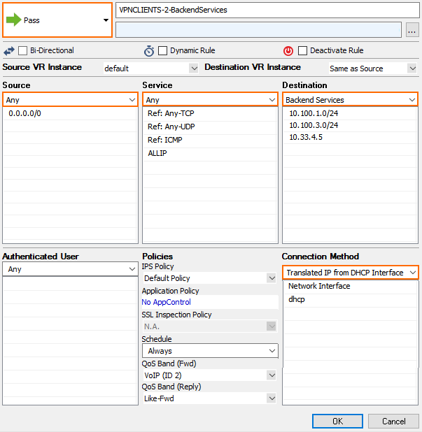
In the TCP Policy section of the Advanced access rule settings:
- Syn Flood Protection (Fwd) – Select Outbound.

In the Dynamic Interface Handling section of the Advanced access rule settings:
- Source Interface – Select VPN Clients.
- Continue on Source Interface Mismatch – Select Yes.

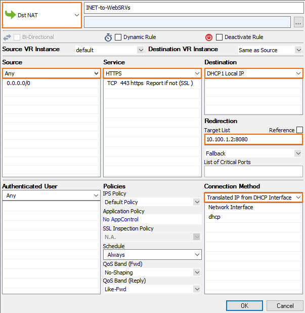
Internet to Backend Services
Create the following access rule to forward traffic from the Internet to an internal web server.

- Action – Select Dst NAT.
- Source – Select Any or a network object containing the networks the ELB is deployed in.
- Service – Select the service. E.g., HTTP+S.
- Destination – Select DHCP1 Local IP.
- Connection Method – Select Dynamic NAT or Translated from DHCP Interface.
Redirection Target – Enter the IP address of the backend service. Optionally, append the port number to redirect to a different port. E.g,
10.100.1.2or10.100.1.2:8080
Redirect Traffic through a WAF Cluster or Other Service Behind an Internal ELB
Services behind an internal ELB can also be forwarded via Dst NAT access rule.

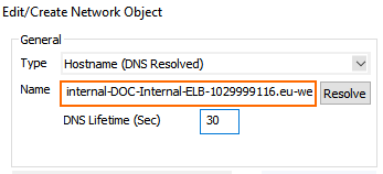
- Create a hostname network object for the internal DNS name of the ELB, set the DNS Lifetime to
30seconds, and click Send Changes.
- Create the access rule:
- Action – Select Dst NAT.
- Source – Select Any or a network object containing the networks the ELB is deployed in.
- Service – Select the service. E.g., HTTP+S.
- Destination – Select DHCP1 Local IP.
- Connection Method – Select Dynamic NAT or Translated from DHCP Interface.
Redirection Target – Click Reference and select the network object for the ELB.
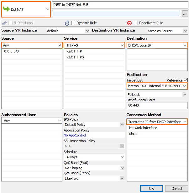
Multiple Backend Services Using the Same Port
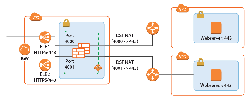
A variation of the same rule, only this time two services running on the same port must be accessed. The ELBs in front of the firewall cluster map the service to different ports on the firewall. The firewall forwards the traffic to the correct instance or internal ELB and maps it back to the correct port.

- Add one ELB per service to the firewall cluster. Map the external port to a unique internal port. E.g., ELB1: 443 -> 4000 and ELB2 443 -> 4001
- Create service objects for the internal ports on the firewall. Optionally, add Port Protocol Detection.
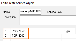
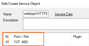
- Create the Dst NAT access rule for the first backend service:
- Action – Select Dst NAT.
- Source – Select Any or a network object containing the networks the ELB is deployed in.
- Service – Select the service object for the first service. E.g,
webApp1-HTTPS - Destination – Select DHCP1 Local IP.
- Connection Method – Select Dynamic NAT or Translated from DHCP Interface.
Redirection Target – Enter the IP address and port of the first backend service. E.g.,
10.100.1.2:443
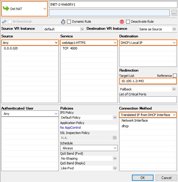
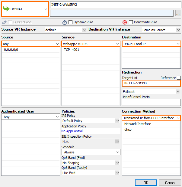
- Create the Dst NAT access rule for the second backend service
- Action – Select Dst NAT.
- Source – Select Any or a network object containing the networks the ELB is deployed in.
- Service – Select the service object for the first service. E.g,
webApp2-HTTPS - Destination – Select DHCP1 Local IP.
- Connection Method – Select Dynamic NAT or Translated from DHCP Interface.
- Redirection Target – Enter the IP address and port for the second backend service E.g.,
10.111.2.4:443
Enabling IPS per Access Rule
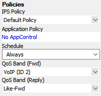
For the Intrusion Prevention System to scan packets matching an access rule, select the IPS Policy in the Pass or Dst NAT access rule. Depending on the configuration of the IPS, malicious traffic patterns are now blocked or reported. For SSL encryption, it is recommended to use SSL offloading on the ELB to allow the IPS to analyze the decrypted traffic. This saves processing power on the firewall. If end-to-end encryption is required for regulatory reasons, enable SSL Inspection on the access rule and in the IPS configuration to also scan SSL-ecrypted traffic.
For step-by-step instructions, see Intrusion Prevention System (IPS).
