

Model 190
Front Panel Power and Disk Activity Indicator Lights
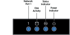
Front Panel Power and Disk Activity Indicator Lights
Component Name | Description |
|---|---|
Power Button | Push to power on the Barracuda Backup appliance, and tap to safely reboot the appliance. |
Reset Button | Push for 5 seconds to reset the Barracuda Backup appliance. |
Power Indicator Light | Displays a solid blue light when the system is powered on. |
HDD Disk Indicator Light | Displays a solid green light and blinks during disk activity. |
Rear Panel Ports and Connectors
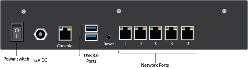
Rear Panel Rear Panel Ports and Connectors Description
Port/Connector Name | Description |
|---|---|
Power Switch | Power switch. |
Power Supply | 12V DC. |
Console | Console connection. |
2 x USB 3.0 Ports | Optional. USB device connection. |
Reset | Push for 5 seconds to reset the Barracuda Backup appliance. |
5 x Network Ports | Network connection. |
Model 290
Front Panel Power and Disk Activity Indicator Lights
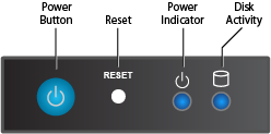
Front Panel Power and Disk Activity Indicator Lights Description
Component Name | Description |
|---|---|
Power Button | Push to power on the Barracuda Backup appliance, and tap to safely reboot the appliance. |
Reset Button | Push for 5 seconds to reset the Barracuda Backup appliance. |
Power Indicator Light | Displays a solid blue light when the system is powered on. |
HDD Disk Indicator Light | Displays a solid green light and blinks during disk activity. |
Rear Panel Ports and Connectors
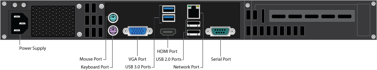
Rear Panel Rear Panel Ports and Connectors Description
Port/Connector Name | Description |
|---|---|
Power Supply | Power supply input. |
Mouse Port | Optional. Mouse port. |
Keyboard Port | Optional. PS2 keyboard connection. |
VGA Port | Recommended. Video graphics array (VGA) monitor connection. |
2 x USB 3.0 Ports | Optional. USB device connection. |
HDMI Port | Optional. HDMI video connection. |
2 x USB 2.0 Ports | Optional. USB device connection. |
Network Port | Network connection. |
Serial Port | Optional. Serial device connection. |
Model 390
Front Panel Indicators, Ports, and Connectors
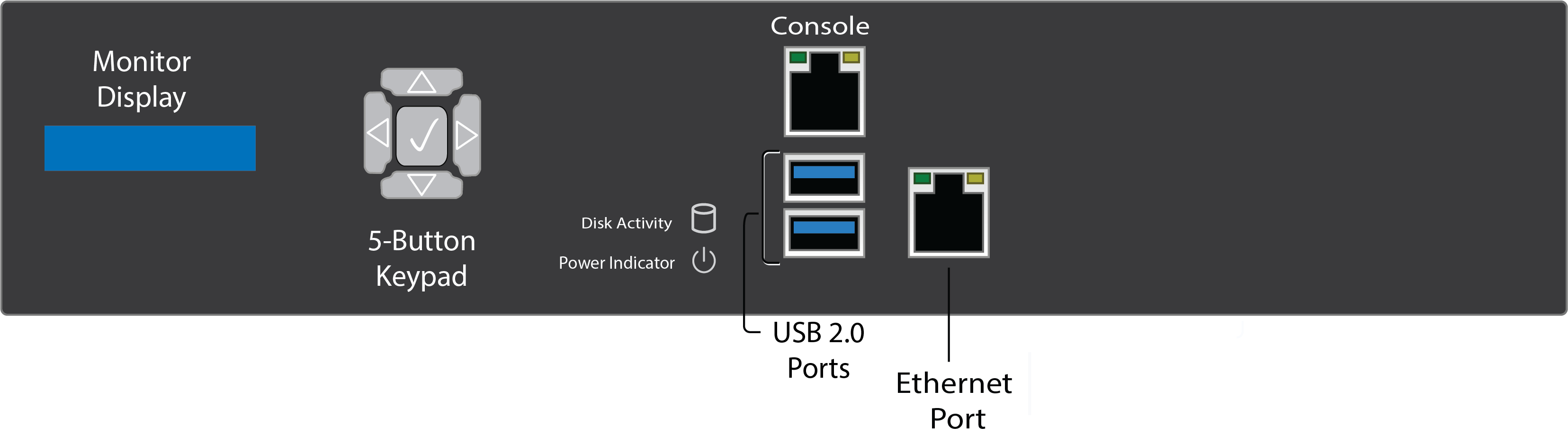
Front Panel Indicators, Ports, and Connectors Description
Component Name | Description |
|---|---|
Liquid Crystal Monitor Display | Currently not active, logo only. |
5-button Keypad | Currently not active. |
HDD Disk Indicator Light | Displays a solid green light and blinks during disk activity. |
Power Indicator Light | Displays a solid blue light when the system is powered on. |
Console Port (RJ-45) | Currently not active. |
2 x USB 2.0 Ports | Optional. USB device connection. |
1 GB Ethernet Port (RJ-45) | Network Connection. |
Note that the Liquid Crystal Monitor (1) and Console Port (RJ-45) are currently not activated.
Rear Panel Ports and Connectors
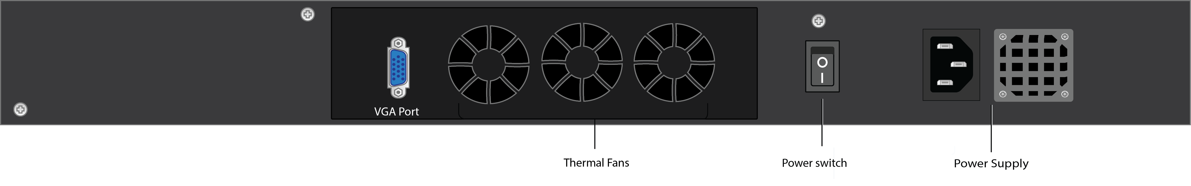
Rear Panel Rear Panel Ports and Connectors Description
Port/Connector Name | Description |
|---|---|
VGA Port | Recommended. Video graphics array (VGA) monitor connection. |
Thermal FAN | Thermal fan vents. |
Power switch | Power switch. |
AC Inlet (250W PSU) | Power supply unit. |
Models 490, 690, 3024
Front Panel Indicators, Ports, and Connectors
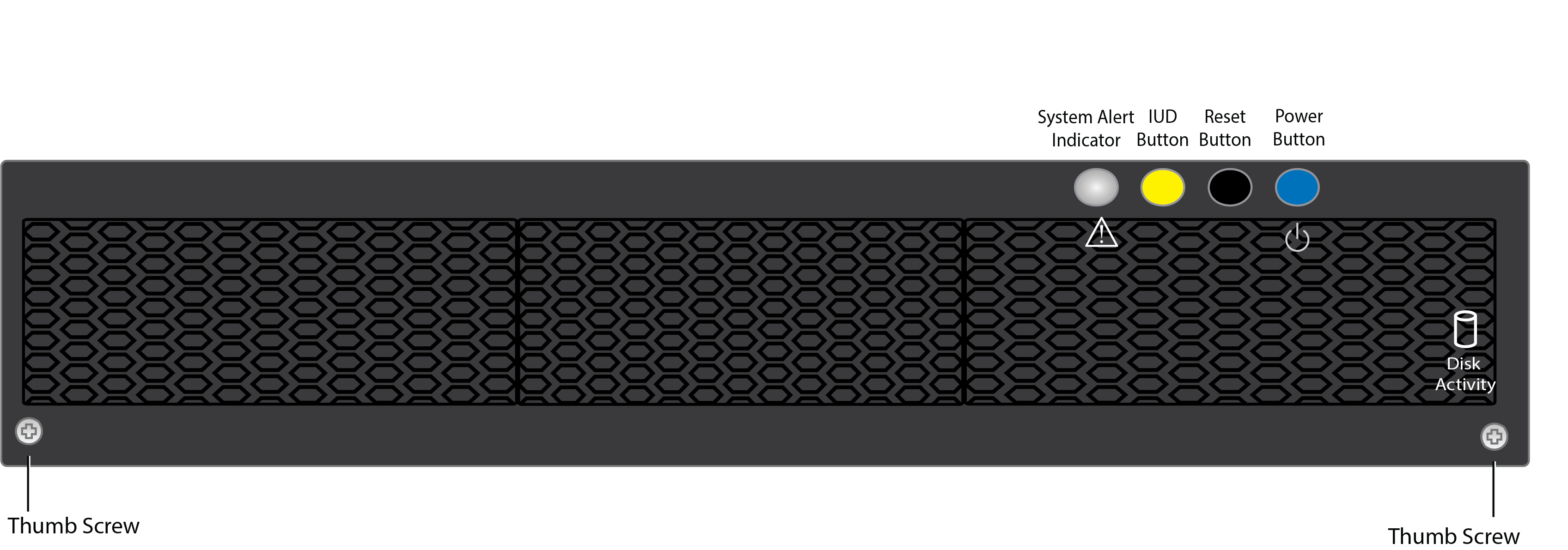
Front Panel Indicators, Ports, and Connectors Description
Component Name | Description |
|---|---|
2 x Front Cover Thumb Screw | Front cover can be removed to display indicator lights. |
HDD Disk Indicator Light | Displays a solid green light and blinks during disk activity. Under front cover. |
System Alert Indicator Light | Sold or blinking red indicates failure. Under front cover. |
Illuminated UID Button | Press to enable UID indicator light (yellow) on rear panel. Under front cover. |
Reset Button | Press to reboot system. Under front cover. |
Power Button | Displays a solid blue light when the system is powered on. Under front cover. |
Rear Panel Ports and Connectors
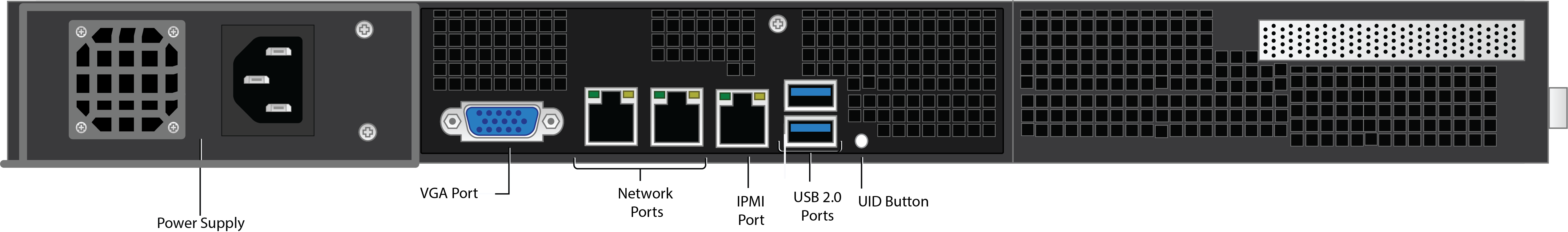
Rear Panel Rear Panel Ports and Connectors Description
Port/Connector Name | Description |
|---|---|
AC Inlet (550W PSU) | Power supply input. |
VGA Port | Recommended. Video graphics array (VGA) monitor connection. |
2 x 10GB Ethernet Port (RJ-45) | Network connection. |
IPMI Port | Currently not active. Intelligent Platform Management Interface. |
2 x USB 2.0 Ports | Optional. USB device connection. |
Illuminated UID Button | Press to enable UID indicator light (yellow) on front panel. |
Model 3004
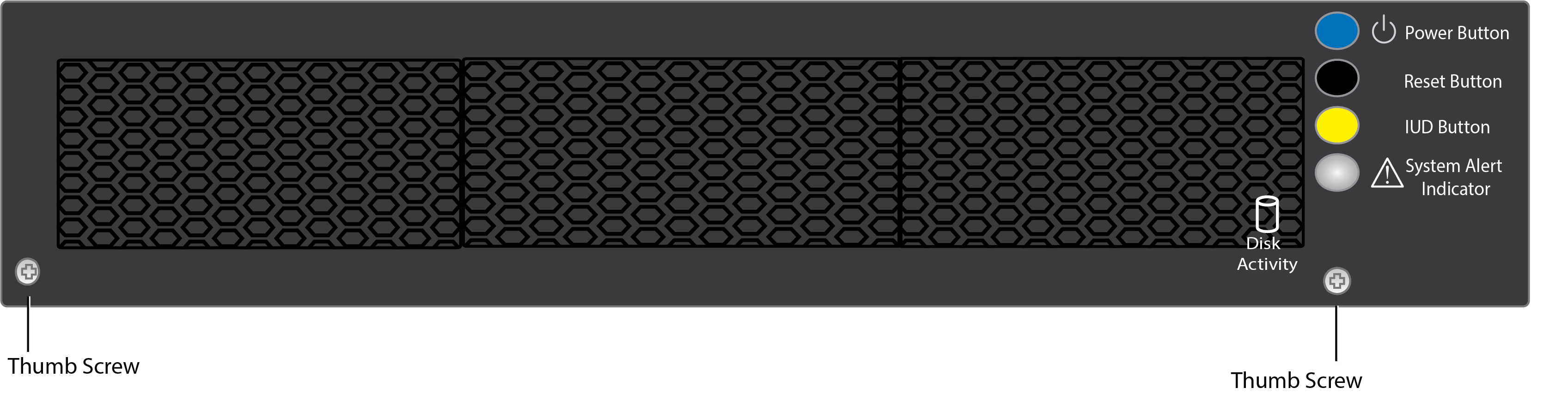
Front Panel Indicators, Ports, and Connectors
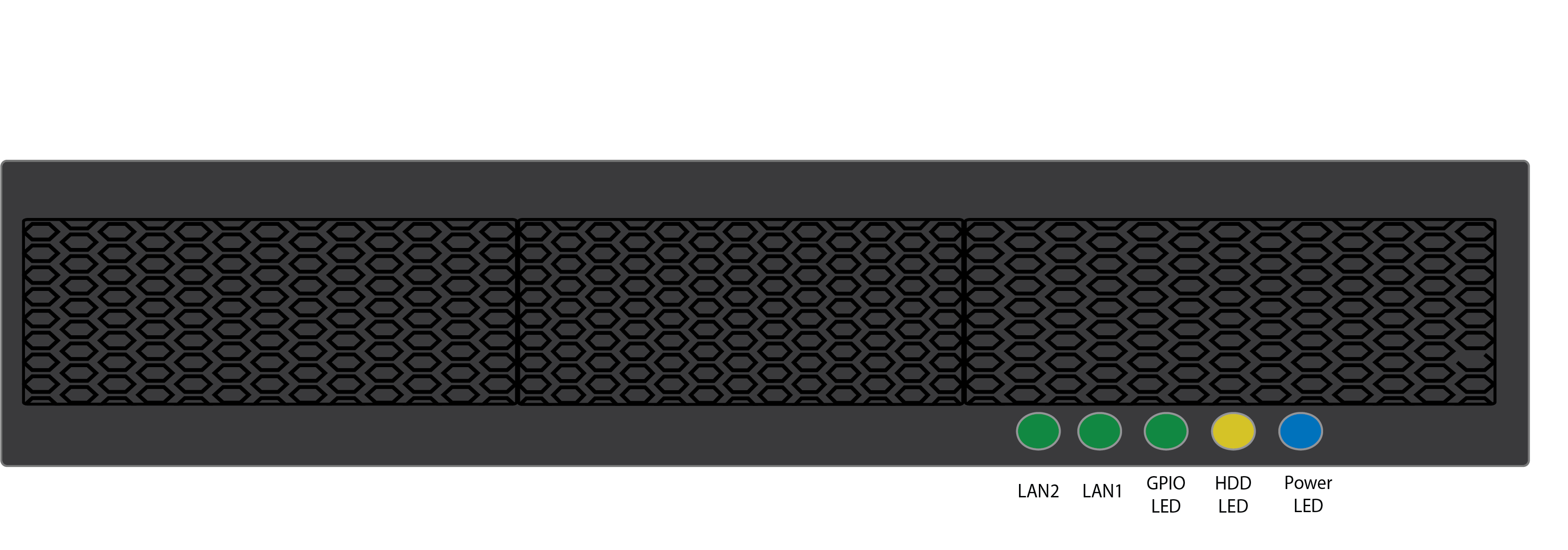
Front Panel Indicators, Ports, and Connectors Description
Component Name | Description |
|---|---|
LAN 2 | Blinking green indicates on. 10Gbps data rate. |
LAN 1 | Blinking green indicates on. 10Gbps data rate. |
GPIO | Blinking green indicates on/off. User-defined via GPIO. |
HDD LED | Blinking yellow indicates HDD/SSD is being accessed. |
Power LED | Blinking blue indicates the system is powered in. |
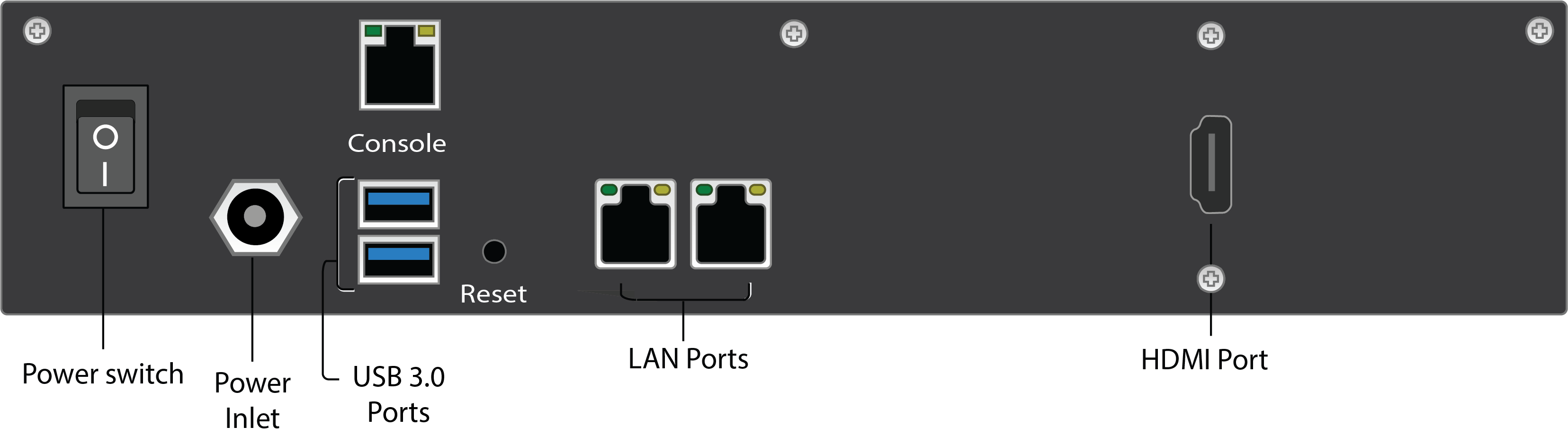
Rear Panel Ports and Connectors
Port/Connector Name | Description |
|---|---|
Power Switch | Power switch. |
Power Inlet | Power inlet. |
Console | Console connections. |
2 x USB 3.0 Ports | Optional. USB device connection. |
2 x 1GB Ethernet Port (RJ-45) | Network connection. |
HDMI Port | Optional. HDMI video connection. |
Models 790, 890, 895, 991, 995, 3080
Front Panel Indicators, Ports, and Connectors
Front Panel Indicators, Ports, and Connectors Description
Component Name | Description |
|---|---|
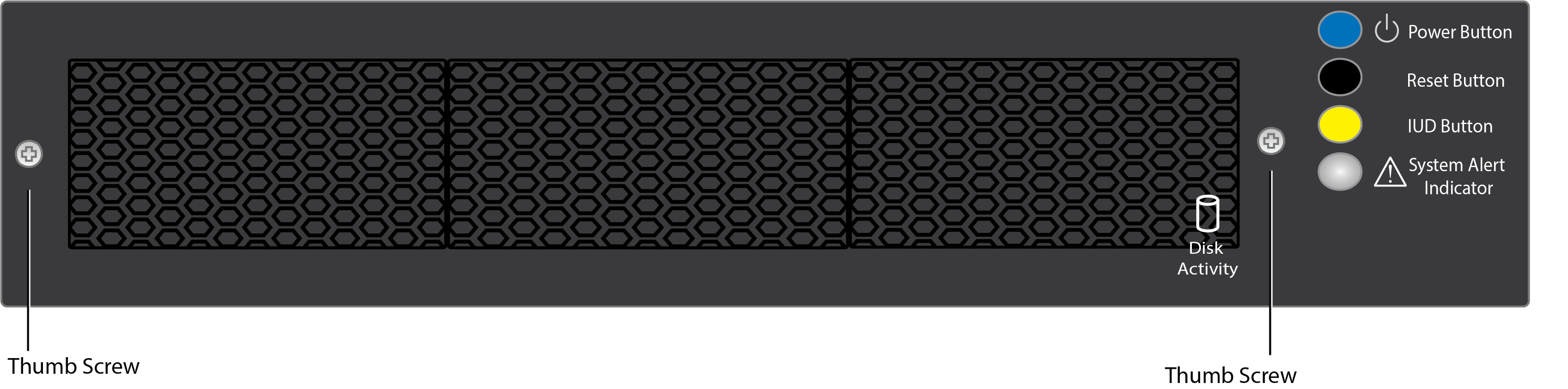
2 x Front Cover Thumb Screw | Front cover can be removed to display indicator lights. |
HDD Disk Indicator Light | Displays a solid green light and blinks during disk activity. Under front cover. |
System Alert Indicator Light | Sold or blinking red indicates failure. Under front cover. |
Illuminated UID Button | Press to enable UID indicator light (yellow) on rear panel. Under front cover. |
Reset Button | Press to reboot system. Under front cover. |
Power Button | Displays a solid blue light when the system is powered on. Under front cover. |
Rear Panel Ports and Connectors
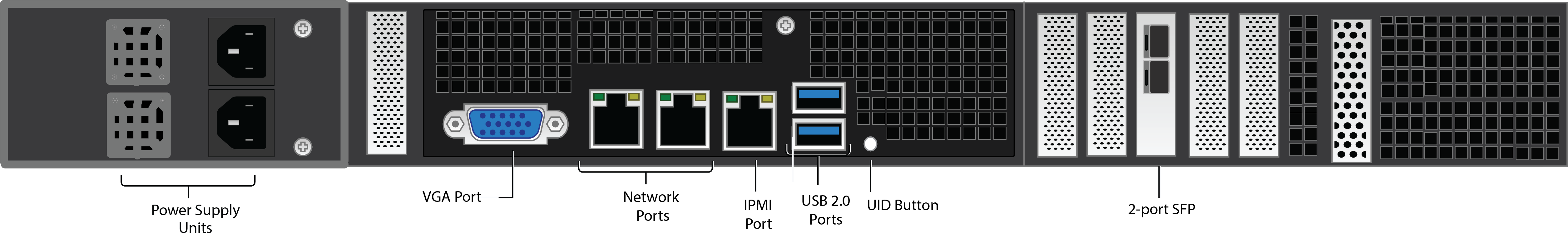
Rear Panel Port and Connector Description
Port/Connector Name | Description |
|---|---|
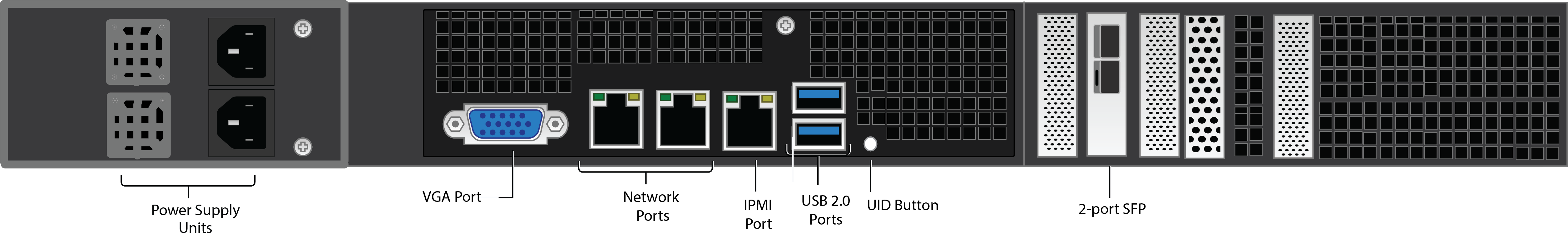
2 x AC Inlet (1300W PSU) | Power supply input. |
VGA Port | Recommended. Video graphics array (VGA) monitor connection. |
2 x 10GB Ethernet Port (RJ-45) | Network connection. |
IPMI Port | Currently not active. Intelligent Platform Management interface. |
2 x USB 2.0 Ports | Optional. USB device connection. |
Illuminated UID Button | Press to enable UID indicator light (yellow) on front panel. |
2 x 10GB Fiber Card | Optional. Use a small form-factor pluggable (SFP) transceiver module:
By default the top port is active. |
Models 1091, 1191, 3200
Front Panel Indicators, Ports, and Connectors
Front Panel Indicators, Ports, and Connectors Description
Component Name | Description |
|---|---|
2 x Front Cover Thumb Screw | Front cover can be removed to display indicator lights. |
HDD Disk Indicator Light | Displays a solid green light and blinks during disk activity. Under front cover. |
System Alert Indicator Light | Sold or blinking red indicates failure. Under front cover. |
Illuminated UID Button | Press to enable UID indicator light (yellow) on rear panel. Under front cover. |
Reset Button | Press to reboot system. Under front cover. |
Power Button | Displays a solid blue light when the system is powered on. Under front cover. |
Rear Panel Ports and Connectors
Rear Panel Port and Connector Description
Port/Connector Name | Description |
|---|---|
2 x AC Inlet (1300W PSU) | Power supply input. |
VGA Port | Recommended. Video graphics array (VGA) monitor connection. |
2 x 10GB Ethernet Port (RJ-45) | Network connection. |
IPMI Port | Currently not active. Intelligent Platform Management interface. |
2 x USB 2.0 Ports | Optional. USB device connection. |
Illuminated UID Button | Press to enable UID indicator light (yellow) on front panel. |
2 x 10GB Fiber Card | Optional. Use a small form-factor pluggable (SFP) transceiver module:
By default the top port is active. |