

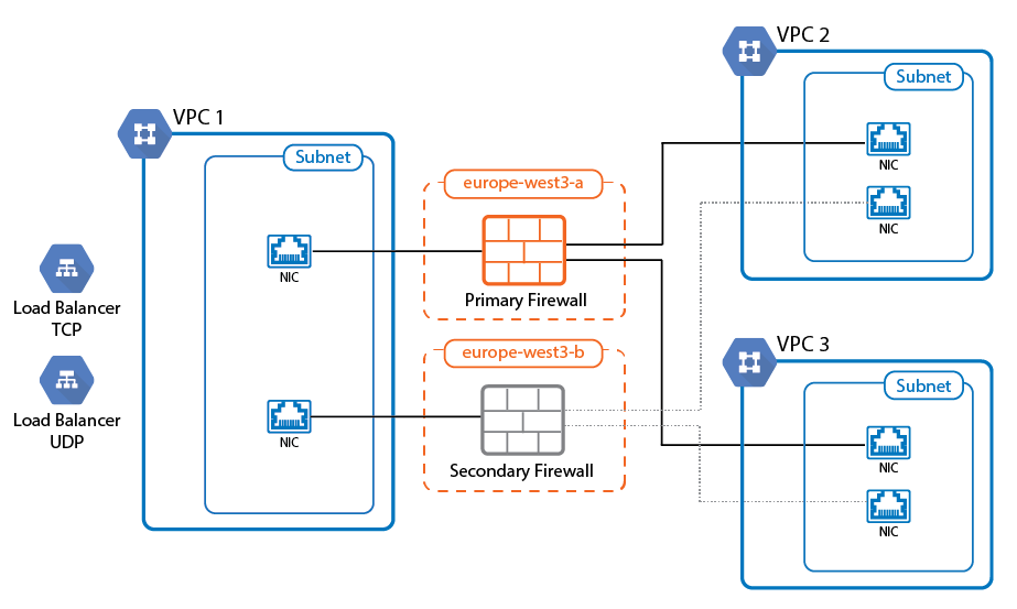
Running your CloudGen Firewall in a High Availability cluster in the Google Cloud ensures that even in the event of a data center failure in the cloud the other firewall can take over and your applications will remain reachable. All VPC networks must be in the same region; however, the two firewall instances are deployed into two different zones inside this region. The firewall instances are configured with one network interface per VPC network. Routing table in the VPC networks are configured to use the firewall as the target for traffic to the Internet and to other VPC networks. This allows the firewall to act both as the default gateway for Internet-bound traffic and as a segmentation firewall to VPC-to-VPC traffic. The number of network interfaces is determined by the number of CPU cores of the selected instance types. For example: for three VPCs, you need an instance with 3 CPU cores or more.
To rewrite the routes using the firewall as the target, a script must be placed in the /opt/phion/hooks/ha/ directory of each firewall. The script is executed every time the service fails over and rewrites the routes to use the active firewall as the target.
To use the High Availability cluster with a single public IP address, add a TCP and/or UDP Google Network Load balancer. To use the load balancer, there must be a service on port 80 or 433 running on or behind the firewall because the Google legacy health check only allows HTTP and HTTP health checks. Use the SSL VPN service or the Cloud landing page. Alternatively, it is also possible to probe a web service behind the firewall, but an outage of the web service would result in the firewall to be considered unhealthy.
Before You Begin
- Download the Google Cloud Image from the Barracuda Networks Download Portal: https://dlportal.barracudanetworks.com.
- Create a custom service account and role for the High Availability cluster. For more information, see How to Create a Custom Role and Service Account for the CloudGen Firewall in the Google Cloud.
- Download the Google Cloud Takeover script needed for Step 18: gcp-ha-takeover.sh
Step 1. Create the Hub VPC Network
Create the virtual private network where the two firewall instances will be running. Create a subnet for the firewall instances.
- Log into the Google Cloud Platform. https://console.cloud.google.com/
- Create a new project or select your project.
- Click the hamburger menu in the upper-left corner.

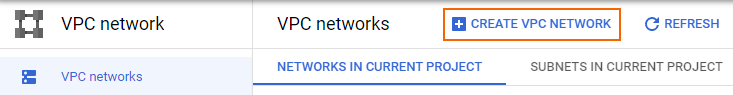
- In the VPC network section, select VPC networks.
- Click CREATE VPC NETWORK.
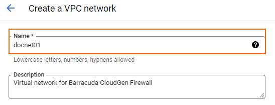
- Enter a Name for your network.
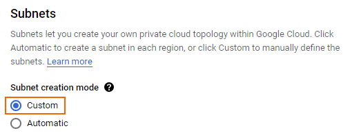
- In the Subnets section, select Custom.
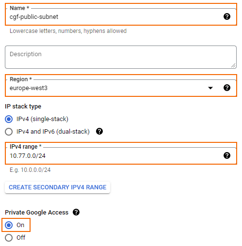
- Create the public subnet:
- Name – Enter
cgf-public-subnet - Region – Select your region. All virtual networks must be in the same region.
- IPv4 range – Enter the network in CIDR format. Do not use a network that overlaps with your on-premises network.
- Private Google Access – Select the radio button.
- Name – Enter
- (optional) For each additional subnet in this virtual network, click ADD SUBNET.
- Click CREATE.
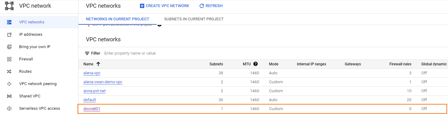
The VPC network for the firewall instances is now listed in the VPC Networks list.
Step 2. Create Additional VPC Networks
Create additional virtual networks with subnets in the same region. The number of virtual networks may not exceed the number of CPU cores on the firewall instance. Verify that the networks of the VPC networks do not overlap.
Step 3. Create Google Firewall Rules
Google firewall rules must be configured for traffic to reach the firewall instances.
- Go to https://console.cloud.google.com.
- Click the hamburger menu in the upper-left corner.
- In the VPC network section, select Firewall.
- Click CREATE FIREWALL RULE.

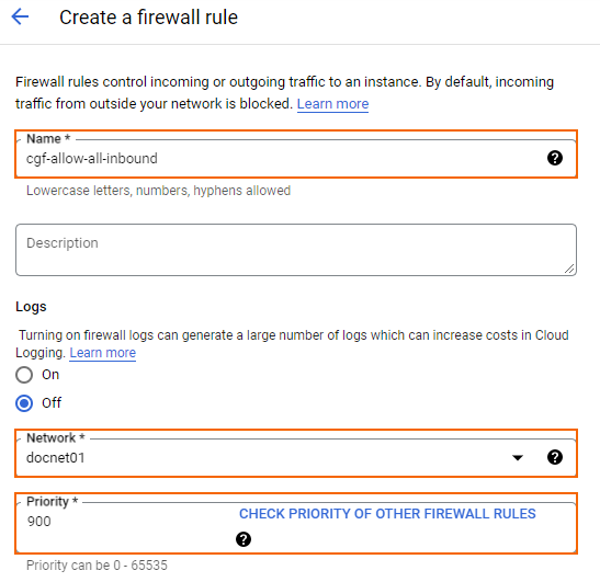
- Create a firewall rule to allow incoming traffic from the Internet to your firewall instances:
- Name – Enter the firewall rule name.
- Network – Select the network created in Step 1.
- Priority – Set a priority lower than 1000.
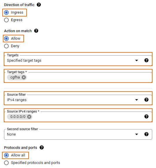
- Direction of traffic – Select Ingress.
- Action on match – Select Allow.
- Targets – Select Specified target tags.
- Target tags – Enter the tag
cgfhathat will be assigned to the firewall instances. - Source filter – Select IPv4 ranges.
- Source IP ranges – Enter
0.0.0.0/0. Protocols and ports – Enter a semicolon-delimited, lower-case list of protocols and ports, or select Allow all.
- Click CREATE.
- In each VPC network, create a firewall rule to allow traffic from selected subnets to the firewall:
- Name – Enter the firewall rule name.
- Network – Select one of the VPC network created in Step 2. Select the VPC network created in Step 1 to allow traffic from private subnets in the hub VPC network to the firewall.
- Priority – Set a priority lower than 1000.
- Action on match – Select Allow.
- Targets – Select Specified target tags.
- Target tags – Enter the tag
cgfhathat will be assigned to the firewall instances. - Source filter – Select Subnetworks.
- Subnetworks – Select the subnets and click OK.
Protocols and ports – Enter a semicolon-delimited, lower-case list of protocols and ports, or select Allow all.
- Click CREATE.
Traffic is now allowed to and from the firewall instances from the Internet and the additional VPC networks, as well as the private networks in the hub VPC network.
Step 4. Create a Storage Bucket and Upload the Disk Image
Upload the disk image to Google Cloud. If the upload through the browser does not work, you can instead use Google Cloud SDK to upload the disk image.
- Go to https://console.cloud.google.com.
- Click the hamburger menu in the upper-left corner.
- In the Cloud Storage section, click Buckets.
- In the main area, click CREATE.
- Create a storage bucket:
- Name – Enter a unique name.
- Region – Select the location matching the region you are deploying in.
- Storage class – Select a storage class depending on your preferences.
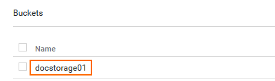
- Click CREATE. The storage bucket is now listed in the Buckets list.
- Click the storage bucket you just created.
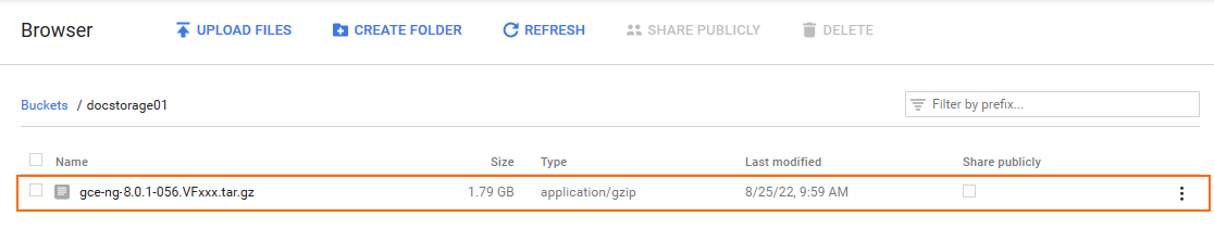
- Click UPLOAD FILES and select the firewall disk image you previously downloaded from the Barracuda Download Portal.
The disk image is now listed in the file list of the storage bucket.
Step 5. Create a Compute Engine Image from the Uploaded Disk Image
To be able to deploy a firewall from the disk image uploaded in Step 3, you must create a Google Compute Engine image. The firewall is created with one dhcp interface. DHCP reservation can be done manually (static) or automatically by Google during deployment. Once assigned, the internal IP address does not change.
- Go to https://console.cloud.google.com.
- Click the hamburger menu in the upper-left corner.
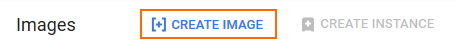
- In the Compute Engine section, select Images.
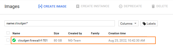
- In the main area, click CREATE IMAGE.
- Create an image using the disk image uploaded in Step 3.
- Name – Enter a name for the firewall image.
- Source – Select Cloud Storage file.
- Cloud Storage File – Click Browse and select the disk image in the storage bucket created in Step 3.
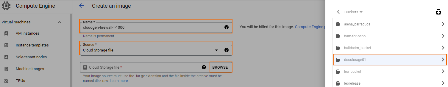
- Click CREATE.
The firewall disk image is now listed in the Images list.
Step 6. Create the Primary Firewall Instance
Launch the primary firewall instance into the public subnet of the hub VPC network. Add one network interface per additional VPC network. The number of CPU cores must be at least equal to the required number of network interfaces.
- Go to https://console.cloud.google.com.
- Click the hamburger menu in the upper-left corner.
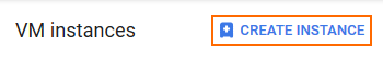
- In the Compute Engine section, click VM instances.
- In the main area, click CREATE INSTANCE.
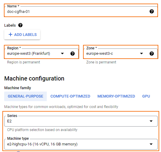
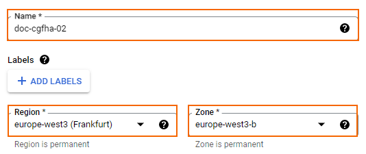
Enter a lowercase Name for the primary firewall instance.
- Select Region and Zone. The instance must be in the same region as the public subnet in the network created in Step 1.
- Select the Machine type. Verify that the number of vCPUs matches the number of cores included in your CloudGen Firewall license and the number of network interfaces used by the instance.
- In the Boot disk section, click Change.
- Click the CUSTOM IMAGES tab.
- Select the disk image you created in Step 5.
- Select the Boot disk type.
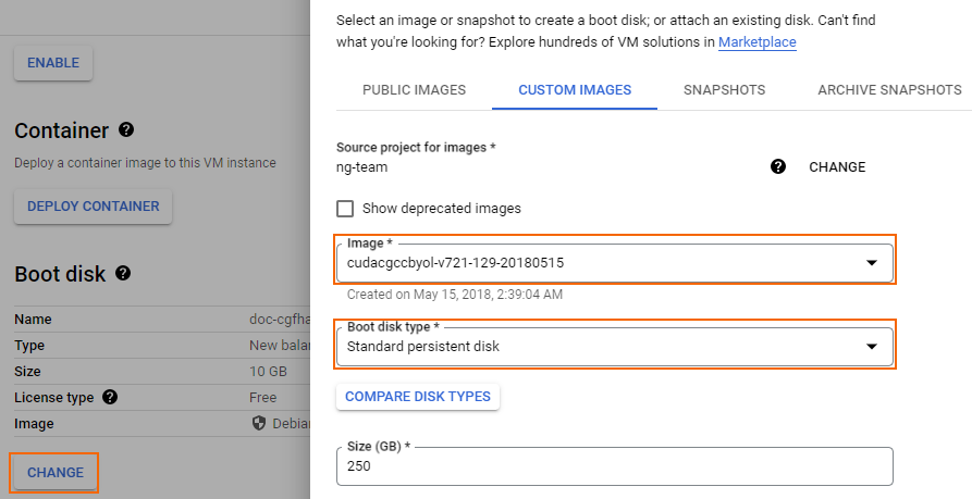
- Click SELECT.
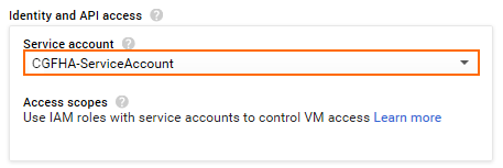
- Select the dedicated Service account associated with the custom role that was created for the High Availability cluster. For more information, see How to Create a Custom Role and Service Account for the CloudGen Firewall in the Google Cloud.
- In the Access scopes section, select Allow full access to all Cloud APIs.
- Below the Firewall section, scroll down and expand Advanced options.
- Expand Networking.
- Add
cgfhato the Network tags.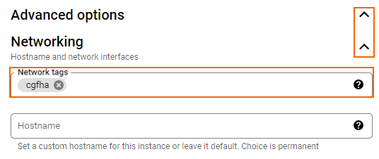
- Select Enable for IP forwarding.
- In the Network interfaces section, edit the default network interface,
- Edit the first network interface:
- Network – Select the network created in Step 1.
- Subnetwork – Select the public subnet created in Step 1.
- Primary Internal IP – Select Ephemeral (Custom). Enter a free IP address in the subnet. The first IP address in the subnet is reserved for the gateway.
- External IPv4 address – Select a reserved external IP address. To use a dynamic public IP address, select Ephemeral.
- For each additional network interface, click ADD NETWORK INTERFACE.
- Configure the additional network interface:
- Network – Select one of the additional VPC networks created in Step 2.
- Subnetwork – Select a subnet in the VPC network that is in the same region as the firewall instance.
- Primary Internal IP – Select Ephemeral (Custom). Enter a free IP address in the subnet. The first IP address in the subnet is reserved for the gateway.
- External IPv4 address – Select None.
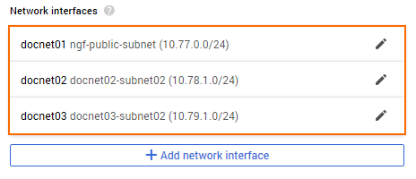
- Click DONE. All network interfaces are now listed in the Network interfaces section.
- Click CREATE.
The primary firewall instance is now started.
Step 7. Create the Secondary Firewall Instance
Deploy the secondary firewall of the High Availability cluster into the same subnet, but in a different zone. This ensures that one firewall of the cluster will always be running, even in case of a data center failure within the Google Cloud. To ease configuration clone the primary firewall and change the configuration to match the settings of the secondary firewall.
- Go to https://console.cloud.google.com.
- Click the hamburger menu in the upper-left corner.
- In the Compute Engine section, select VM instances.
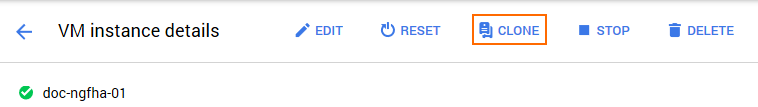
- Click on the primary firewall instance created in Step 4. The VM instance details page opens.

- Click CLONE.
- Enter the Name for the secondary firewall instance.
- Select Region and Zone. Select different zones in the same region for the two firewalls in the High Availability cluster.
- Scroll down and expand Advanced options.
- Expand Networking.
- Add
cgfhato the Network tags. - Select Enable for IP forwarding.
- In the Network Interfaces section, click the edit icon for the default network interface,
- Click the edit icon for the first network interface:
- Network – Select the network created in Step 1.
- Subnetwork – Select the public subnet created in Step 1.
- Primary Internal IP – Select Ephemeral (Custom). Enter a free IP address in the subnet.
- External IPv4 address – Select a reserved external IP address. To use a dynamic public IP address, select Ephemeral.
- Click DONE.
- Click the edit icon for the other network interfaces, and assign free custom internal IP addresses in the subnets.
- Click CREATE.
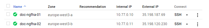
Both the primary and secondary firewalls of the High Availability cluster are now running.
Step 8. Configure a Default Route for the VPC Networks to Use the Primary Firewall
For each VPC network, create a default route for the client instances to use the active firewall as the target.
- Go to https://console.cloud.google.com.
- Click the hamburger menu in the upper-left corner.
- Click VPC network.
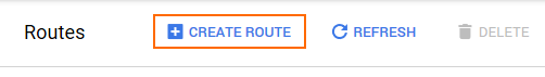
- In the left menu, click Routes.
- Click Create Route.
- Configure the route:
- Name – Enter a name for the route.
- Network – Select the VPC network from the list.
- Destination IP range – Enter
0.0.0.0/0. - Priority – Enter
100. - Next hop – Select Specify an instance.
- Next hop instance – Select the active firewall.
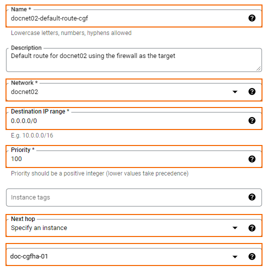
- Click CREATE.
All traffic leaving the VPC is now being sent through the active firewall. If you have attached two additional VPC networks to the firewall, you should have at least two routes: one for each VPC network. If you also have private subnets in the hub VPC network, three routes must be created. The next hop is the IP address of the firewall's network interface in that VPC network subnet.
Step 9. Add an Additional Network Interface to the Primary Firewall Configuration
Add and configure the additional network interfaces on the primary firewall.
Log into the primary firewall:
IP Address – The public IP address listed in the External IP column on the VM Instances page.
User – Enter
rootPassword – The password located in VM instances > your VM instance > Custom metadata.
- Go to CONFIGURATION > Configuration Tree > Box > Network.
- Click Lock.
- In the left menu, select Interfaces.
- Double-click the entry in Network Interface Cards. The Network Interface Configuration window opens.
- Change the Number of Interfaces to the number of interfaces attached to the firewall.
- Click OK.
- Click Send Changes.
- In the left menu, select Advanced Routing.
- In the left menu, expand the Configuration Mode section and click Switch to Advanced.
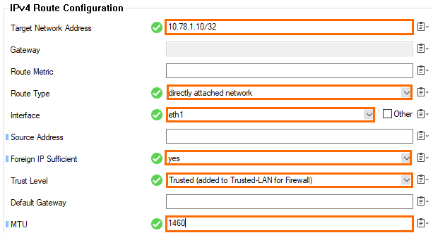
- Click + in the IPv4 Routing Table to create a new direct attached route for private IP address of the network interface:
- Target Network Address – Enter the private IP address of the network interface with a /32 subnet mask E.g.,
10.78.1.10/32 - Route Type – Select directly attached network.
- Interface – Select the network interface. E.g., eth1
- Foreign IP Sufficient – Select yes.
- Trust Level – Select Trusted.
- MTU – Enter
1460.
- Target Network Address – Enter the private IP address of the network interface with a /32 subnet mask E.g.,
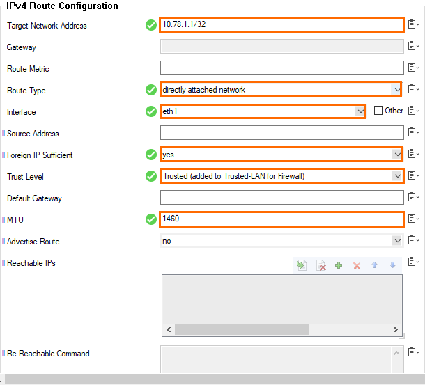
- Click + in the IPv4 Routing Table to create a new direct attached route for the default subnet gateway assigned by Google. The default gateway is always the first IP address in the subnet:
- Target Network Address – Enter the first IP address in the subnet with /32 subnet mask. E.g.,
10.78.1.1/32. - Route Type – Select directly attached network.
- Interface Name – Select the network interface. E.g., eth1
- Foreign IP Sufficient – Select yes.
- Trust Level – Select Trusted.
- MTU – Enter
1460.
- Target Network Address – Enter the first IP address in the subnet with /32 subnet mask. E.g.,
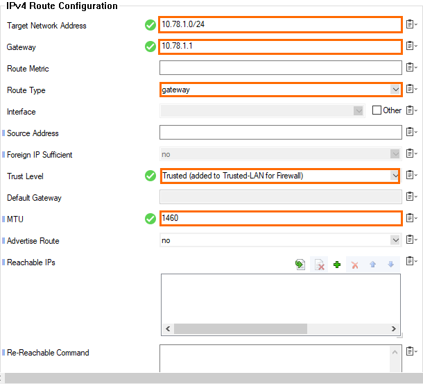
- Click + in the IPv4 Routing Table to create a new gateway route for the subnet using the default subnet gateway:
- Target Network Address – Enter the subnet in CIDR format. E.g.,
10.78.1.0/24 - Route Type – Select gateway.
- Gateway – Enter the first IP address in the subnet. E.g.,
10.78.1.1 - Trust Level – Select Trusted.
- MTU – Enter
1460.
- Target Network Address – Enter the subnet in CIDR format. E.g.,
- Click Send Changes and Activate.
Step 10. Disable ICMP Gateway Monitoring for Additional Network Interfaces
Disable ICMP gateway monitoring for all additional network interfaces.
- Log into the primary firewall.
- Go to CONFIGURATION > Configuration Tree > Box > Infrastructure Services > Control.
- Click Lock.
- For each additional network interface click + to add an entry in the No Probing for Interfaces table,
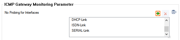
- If the interface is not in the list, enter it in the Other field.
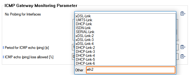
- Click Send Changes and Activate.
Step 11. Change the Primary Firewall Configuration to Use the Static Network Interface
- Log into the primary firewall.
- Go to CONFIGURATION > Configuration Tree > Box > Network.
- In the left menu, expand the Configuration Mode section and click Switch to Advanced.
- Click Lock.
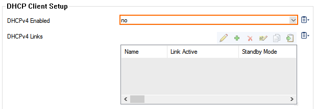
- in the left menu, click xDSL/DHCP.
- Delete the DHCP01 entry in the DHCP Links list.
- Select No from the DHCPv4 Enabled drop-down list.
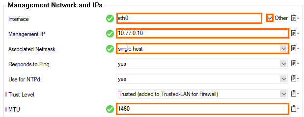
- In the left menu, click IP Configuration.
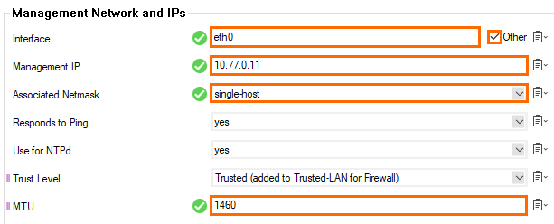
- In the Management Network and IPs section, reconfigure the management IP:
- Interface Name – Select Other and enter
eth0. - Management IP – Enter the private IP address of the primary firewall. Go to CONTROL > Network. The private IP address is assigned to the dhcp interface.
- Associated Netmask – Select single-host.
- MTU – Enter
1460.
- Interface Name – Select Other and enter
- In the left menu, click Advanced Routing.
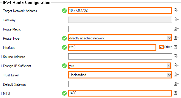
- Click + in the IPv4 Routing Table to create a new direct attached route for the default subnet gateway assigned by Google. The default gateway is always the first IP address in the subnet:
- Target Network Address – Enter the first IP address in the subnet with /32 subnet mask. E.g., 10.77.0.1/32
- Route Type – Select directly attached network.
- Interface Name – Select Other and enter
eth0. - Foreign IP Sufficient – Select yes.
- Trust Level – Select Unclassified.
- MTU – Enter
1460.
- Click OK.
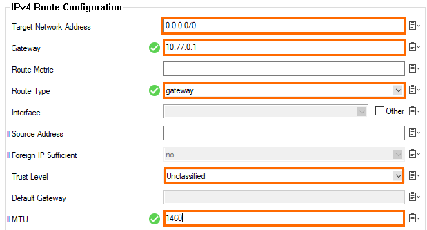
- Click + in the IPv4 Routing Table and add the default route:
- Target Network Address – Enter
0.0.0.0/0. - Gateway – Enter the first IP address in the subnet. E.g.,
10.77.0.1 - Route Type – Select gateway.
- Trust Level – Select Unclassified.
- MTU – Enter
1460.
- Target Network Address – Enter
- Click OK.
- Click Send Changes and Activate.
Open the CONTROL > Network page. Your interface and IP address are now static.
Step 12. Activate the Network Changes
- Go to CONTROL > Box.
- In the left menu, expand the Network section and click Activate new network configuration.
Select Failsafe.
Step 13. Configure the DNS Server
Add the first IP address of the subnet as the DNS server (e.g., 10.77.0.1). Do not use external DNS servers because, otherwise, it is not possible to resolve the internal Google metadata service used by the HA failover script.
For more information, see How to Configure DNS Settings.
Step 14. Configure the Management IP and Network on the Primary Firewall
- Log into the primary firewall.
- Go to CONFIGURATION > Configuration Tree > Box > Network.
- In the left menu, expand the Configuration Mode section and click Switch to Advanced.
- In the left menu click IP Configuration.
- In the Management IP and Network section, reconfigure the management IP:
- Interface – Select Other and enter
eth0. - Management IP – Enter the private IP address of the secondary firewall. On the secondary firewall, go to CONTROL> Network. The private IP address is assigned to the dhcp interface.
- Associated Netmask – Select single-host.
- MTU – Enter
1460.
- Interface – Select Other and enter
- Edit the directly attached routes for the private IP addresses to match the secondary firewall custom internal IP address on that network interface.
- In the left menu, click Advanced Routing.
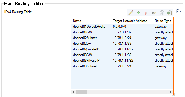
- Verify that the routing is configured analog to the primary firewall:
- For the hub VPC network – One gateway route and one directly attached route.
- For each additional VPC network – One gateway and two directly attached routes. The directly attached routes for the private IP addresses must be changed to match the custom internal IP addresses of the secondary firewall on that interface.
- Click Send Changes and Activate.
Step 15. Add the Private IPs to the Shared IPs
Add the custom private IP addresses of both firewalls to the additional network interfaces to the shared IP addresses, e.g., 10.78.1.10, 10.78.1.11, 10.79.1.10 and 10.79.1.11.
- Log into the primary firewall
- Go to CONFIGURATION > Configuration Tree > Box > Network.
- Click Lock.
- In the left menu, click IP Configuration.
- In the Shared Networks and IPs section, double-click on the entry of the network where the IP address is attached to, or click + to create a new entry.
- The Shared Network and IPs window opens.
- In the Shared IPs in this Network section, click +.
- IP Address – Enter the IP address.
- Alias for this IP– Select None.
- Responds to Ping– Select yes.
- Click OK to save this settings.
- Click OK to save this settings.
- In the Shared IPs in this Network section, click +.
- Click Send Changes and Activate.
- Go to CONTROL > Box.
- In the left menu, expand the Network section and click Activate new network configuration.
Select Failsafe.
Step 16. Create a High Availability Cluster
Create a high availability cluster on your primary firewall and join it with the secondary firewall.
For more information, see How to Set Up a High Availability Cluster.
Step 17. Activate and License the High Availability Cluster
Activate and license the High Availability cluster. Activate the secondary firewall first. Then, activate the primary firewall.
For more information, see How to Activate and License a Standalone High Availability Cluster.
Step 18. (optional) Add the Google Network Load Balancer
To use only one public-facing IP address, it is also possible to use the Google Network Load Balancer in front of the High Availability cluster. To use the load balancer, a service on port 80 or 443 must be reachable for the health check of the load balancer. TCP and UDP services require separate load balancers. To use a service on the firewall for probing create an App Redirect rule redirecting HTTP traffic to the fwauth daemon running on 127.0.0.1:451.
For more information, see https://cloud.google.com/compute/docs/load-balancing/network/